365
Command and Response Formats Section 6-2
Example Program for FCS This example shows a BASIC subroutine program for executing an FCS check
on a frame received by the host computer.
400 *FCSCHECK
410 L=LEN(RESPONSE$) ’ .......... Data transmitted and received
420 Q=0:FCSCK$=” ”
430 A$=RIGHT$(RESPONSE$,1)
440 PRINT RESPONSE$,A$,L
450 IF A$=”*” THEN LENGS=LEN(RESPONSE$)-3
ELSE LENGS=LEN(RESPONSE$)-2
460 FCSP$=MID$(RESPONSE$,LENGS+1,2) ’ ... FCS data received
470 FOR I=1 TO LENGS ’ .......... Number of characters in FCS
480 Q=ASC(MID$(RESPONSE$,I,1)) XOR Q
490 NEXT I
500 FCSD$=HEX$(Q)
510 IF LEN(FCSD$)=1 THEN FCSD$=”0”+FCSD$ ’ ..... FCS result
520 IF FCSD$<>FCSP$ THEN FCSCK$=”ERR”
530 PRINT”FCSD$=”;FCSD$,”FCSP$=”;FCSP$,”FCSCK$=”;FCSCK$
540 RETURN
Note 1. Normal reception data includes the FCS, delimiter or terminator, and so
on. When an error occurs in transmission, however the FCS or some other
data may not be included. Be sure to program the system to cover this pos-
sibility.
2. In this program example, the CR code (CHR$(13)) is not entered for RE-
SPONSE$. When including the CR code, make the changes in lines 430
and 450.
6-2-2 Commands from the PC (CQM1/SRM1 Only)
In host link communications, commands are ordinarily sent from the host
computer to the PC, but it is also possible for commands to be sent from the
PC to the host computer. In Host Link Mode, any data can be transmitted from
the PC to the host computer. To send a command to the host computer, use
the TRANSMIT instruction (TXD(48)) in the PC program in Host Link Mode.
TXD(48) outputs data from the specified port (the RS-232C port or the periph-
eral port). Refer to page 350 for details on using TXD(48).
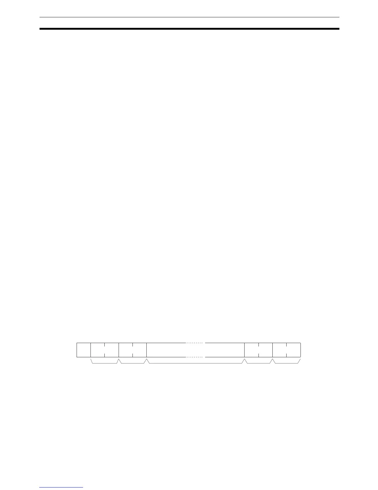
Reception Format When TXD(48) is executed, the data stored in the words beginning with the
first send word is converted to ASCII and output to the host computer as a
host link command in the format shown below. The “@” symbol, node number,
header code, FCS, and delimiter are all added automatically when the trans-
mission is sent. At the host computer, it is necessary to prepare in advance a
program for interpreting and processing this format.
One byte of data (2 digits hexadecimal) is converted to two characters in
ASCII for transmission, the amount of data in the transmission is twice the
amount of words specified for TXD(48). The maximum number of characters
for transmission is 122 and the maximum number of bytes that can be desig-
nated for TXD(48) is one half of that, or 61.
6-2-3 Response End Codes
Refer to 8-7 Host Link Errors for a table listing the response end codes that
may be returned in host link communications. An end code of 00 indicates
normal completion of a command.
@ EX
FCS
Node no. Header code
(Must be "EX")
Tex t
122 characters max.
Terminator
*

 Loading...


