398
CQM1 Cycle Time and I/O Response Time Section 7-1
The maximum I/O response time is as follows:
Input ON delay: 8 ms
Master cycle time: 10 ms
× 2
Transmission time: 39 ms
× 3
Slave cycle time: 15 ms
× 2
+ Output ON delay: 10 ms
Maximum I/O response time:185 ms
7-1-5 Interrupt Processing Time
This section explains the processing times involved from the time an interrupt
is executed until the interrupt processing routine is called, and from the time
an interrupt processing routine is completed until returning to the original posi-
tion. The explanation applies to the following three types of interrupts: input
interrupts, interval timer interrupts, and high-speed counter interrupts.
Processing Time The table below shows the times involved from the generation of an interrupt
signal until the interrupt processing routine is called, and from when the inter-
rupt processing routine is completed until returning to the original position.
Note 1. When high-speed counter 0 is used with a range comparison table, the tim-
ing of interrupt processing can be affected by the cycle time.
2. When high-speed counters 1 and 2 are used with range comparison tables
(in CQM1-43/44-EV1 CPU Units), the timing of interrupt processing can be
delayed up to 1 ms.
Mask Processing
Interrupts are masked during processing of the operations described below.
Until the processing is completed, any interrupts will remain masked for the
indicated times.
High-speed timers:The time shown below is required, depending on (a) the
number of timers used with TIMH(15) and (b) the number
of high-speed timers active at that time. (The number of
high-speed timers is set in the PC Setup, DM 6629. The
default setting is 16.)
0
≤ Standby time ≤ 50 + 3 × (a + b) µs
Up to 50
µs can be required even when no high-speed
timers are used.
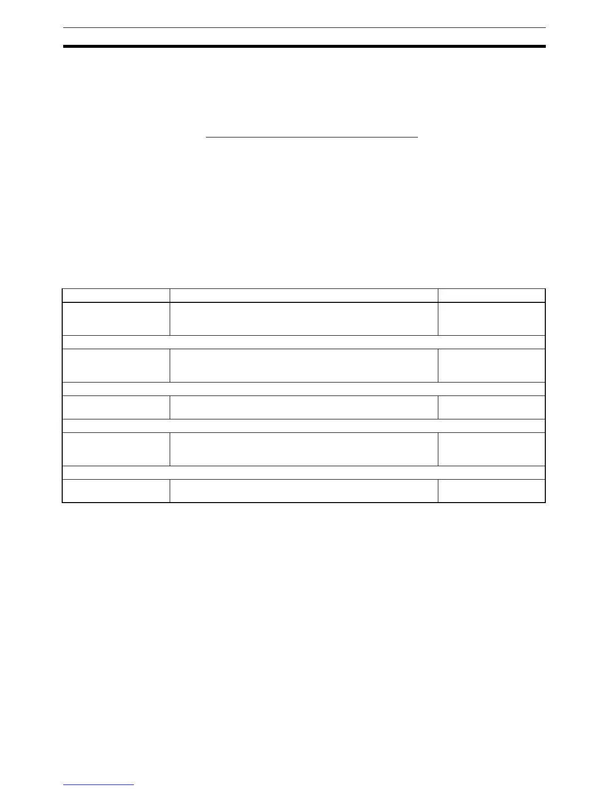
Item Contents Time
Interrupt input ON delay This is the delay time from the time the interrupt input bit turns ON
until the time that the interrupt is executed. This is unrelated to
other interrupts.
50 µs
↓ (Interrupt condition realized.) (see note)
Standby until completion
of interrupt-mask pro-
cessing
This is the time during which interrupts are waiting until processing
has been completed. This situation occurs when a mask pro-
cesses is executed. It is explained below in more detail.
See below.
↓
Change-to-interrupt pro-
cessing
This is the time it takes to change processing to an interrupt. 40 µs
↓
Input refresh at time of
interrupt
This is the time required for input refresh when input refresh is set
to be executed at the time the interrupt processing routine is
called. (Set in PC Setup, DM 6630 to DM 6638.)
10 µs per word
↓ (Interrupt processing routine executed)
Return This is the time it takes, from execution of RET(93), to return to the
processing that was interrupted.
40 µs

 Loading...


