50
CQM1 Interrupt Functions Section 1-5
Wiring Depending on the count mode, the input signals from the pulse encoder to the
CPU Unit’s input terminal are as shown below.
If only the software reset is to be used, terminal 6 can be used as an ordinary
input. When in Incrementing Mode, terminal 5 can be used as an ordinary
input.
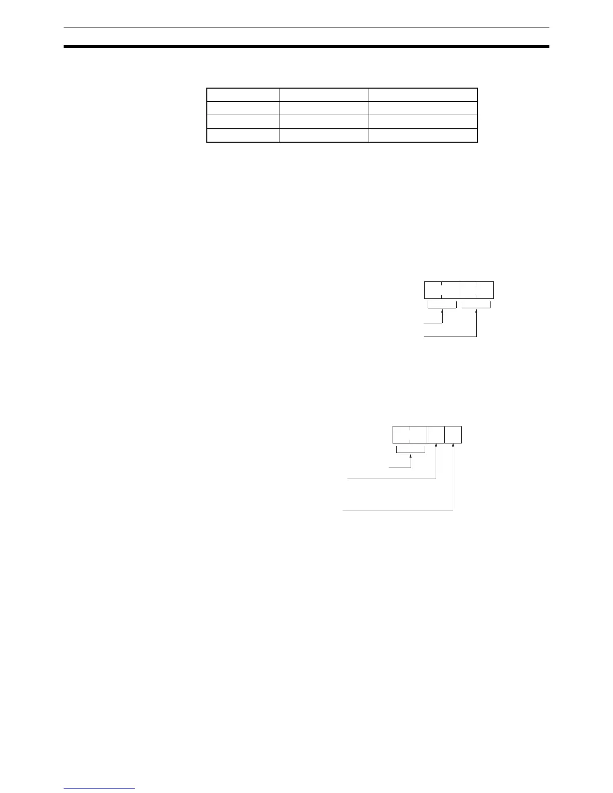
PC Setup When using high-speed counter 0 interrupts, make the settings in PROGRAM
mode shown below before executing the program.
Input Refresh Word Settings (DM 6638)
Make these settings when it is necessary to refresh inputs. The setting is the
same as that for interval timer 2.
High-speed Counter 0 Settings (DM 6642)
If these settings are not made, high-speed counter 0 cannot be used in the
program.
Changes in the setting in DM 6642 are effective only when power is turned on
or PC program execution is started.
Programming Use the following steps to program high-speed counter 0.
High-speed counter 0 begins the counting operation when the proper PC
Setup settings are made, but comparisons will not be made with the compari-
son table and interrupts will not be generated unless the CTBL(63) instruction
is executed.
High-speed counter 0 is reset to “0” when power is turned ON and when oper-
ation begins.
The present value of high-speed counter 0 is maintained in SR 230 and
SR 231.
Terminal no. Up/Down Mode Incrementing Mode
4 Encoder A-phase Pulse count input
5 Encoder B-phase ---
6 Encoder Z-phase Reset input
15 0
DM6638
Bit
Number of words (2 digits BCD) 00 to 12
Beginning word no. (2 digits BCD) 00 to 11
Default: No input refresh
High-speed counter 0 used.
15 0
DM6642
Bit
0 1
Reset method
0: Z-phase and software reset
1: Software reset
Count mode
0: Up/Down Mode
4: Incrementing Mode
Default: High-speed counter 0 not used.