72
CPM1/CPM1A Interrupt Functions Section 1-6
Program Example
When input 00003 (interrupt no. 0) goes ON, operation moves immediately to
the interrupt program with subroutine number 000. Inputs for DM 6628 have
been set to 0001.
Counter Mode External signal inputs are counted at high speed and an interrupt is generated
when the count reaches the set value. When an interrupt is generated, the
main program is interrupted and the interrupt program is executed. Signals up
to 1 kHz can be counted.
Use the following steps to program input interrupts using the Counter Mode.
1,2,3... 1. Write the set values for counter operation to the SR words shown in the fol-
lowing table. The set values are written between 0000 and FFFF (0 to
65,535). A value of 0000 will disable the count operation until a new value
is set and step 2, below, is repeated.
The SR words used in the Counter Mode (SR 240 to SR 243) contain hexa-
decimal data, not BCD. If the Counter Mode is not used, these words can
be used as work bits.
Note These SR words are cleared at the beginning of operation, and must
be written from the program.
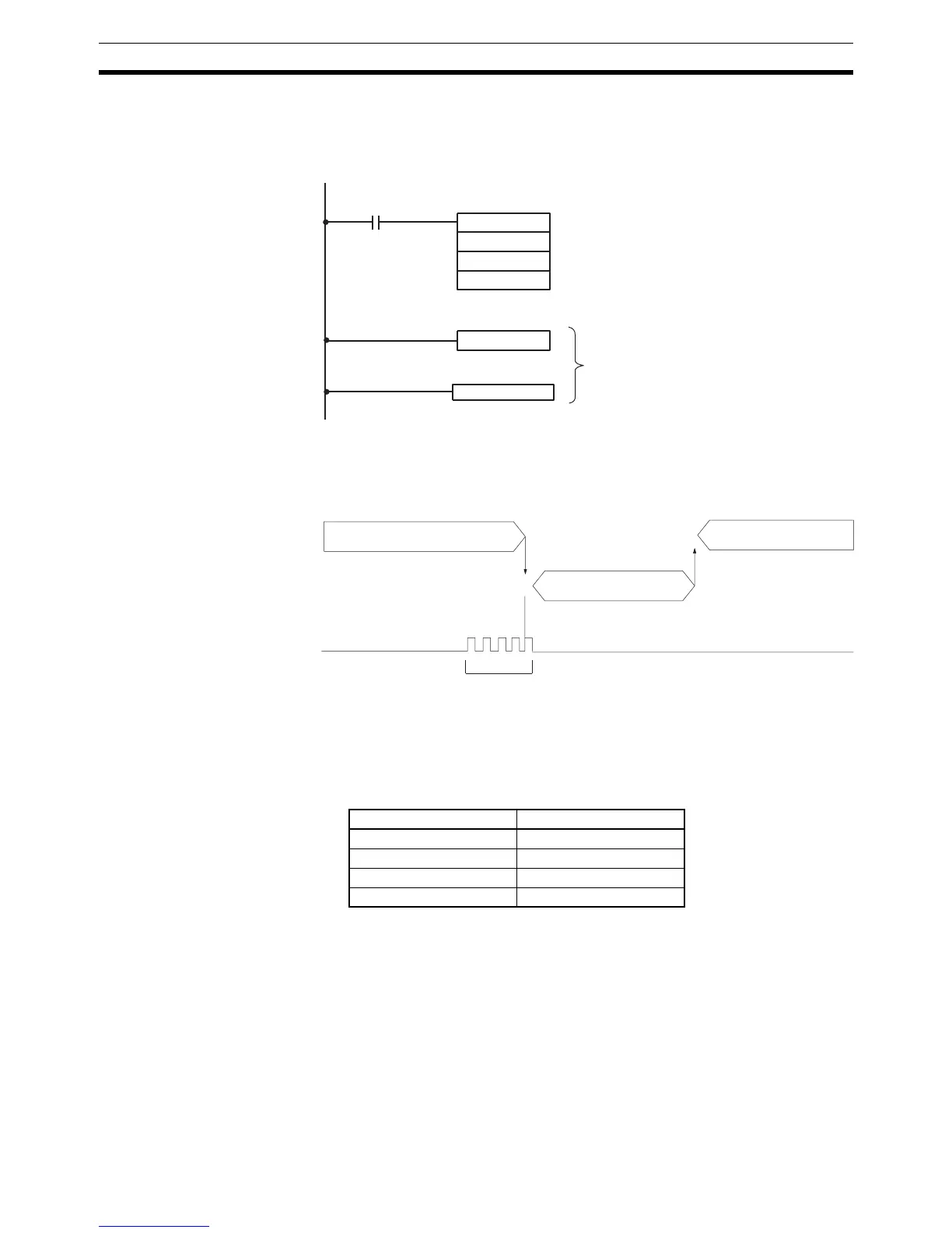
RET(93)
SBN(92) 000
25315 First Cycle Flag
ON for 1 cycle
Interrupt program
@INT(89)
000
000
#000E
Mask/unmask input interrupts.
Unmasks 00003 (interrupt input 0), masks others.
Set value
Main program
Interrupt program
Main program
Input interrupt
Interrupt Word
Input interrupt 0 SR 240
Input interrupt 1 SR 241
Input interrupt 2 SR 242
Input interrupt 3 SR 243
 Loading...


