3 - 7
3 Specifications
OMNUC G5-series (Pulse-train Input Type) AC Servomotors and Servo Drives User’s Manual
3-1 Servo Drive Specifications
3
3-1-3 Main Circuit and Motor Connections
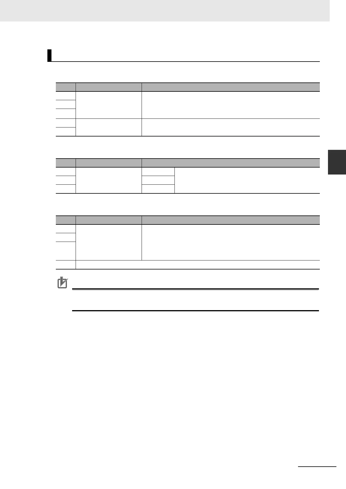
Main Circuit Connector Specifications (CNA)
Motor Connector Specifications (CNB)
External Regeneration Resistor Connector Specifications (CNC)
Precautions for Correct UsePrecautions for Correct Use
• Tighten the ground screws to a torque of 0.7 to 0.8 N·m (M4) or 1.4 to 1.6 N·m (M5).
• Do not connect any External Regeneration Resistors between B1 and NC.
R88D-KP20H
Symbol
Name Function
L1 Main circuit power supply
input
R88D-KPH (2 kW):
3-phase 200 to 230 VAC (170 to 253 VAC) 50/60 Hz
Note Single-phase power supply must be connected to L1 and L3.
L2
L3
L1C Control circuit power
supply input
R88D-KPH: Single-phase 200 to 230 VAC (170 to 253 VAC) 50/60 Hz
L2C
Symbol
Name Function
U Motor connection
terminals
Phase U These are the output terminals to the Servomotor.
Be sure to wire them correctly.
V Phase V
W Phase W
Symbol
Name Function
B1 External Regeneration
Resistor connection
terminals
Normally B2 and B3 are shorted. Do not short B1 and B2. Doing so may
result in a malfunction.
If there is high regenerative energy, remove the short-circuit bar between
B2 and B3 and connect an External Regeneration Resistor between B1 and
B2.
B3
B2
NC Do not connect.

 Loading...


