3 - 23
3 Specifications
OMNUC G5-series (Pulse-train Input Type) AC Servomotors and Servo Drives User’s Manual
3-1 Servo Drive Specifications
3
3-1-6 Control Input Details
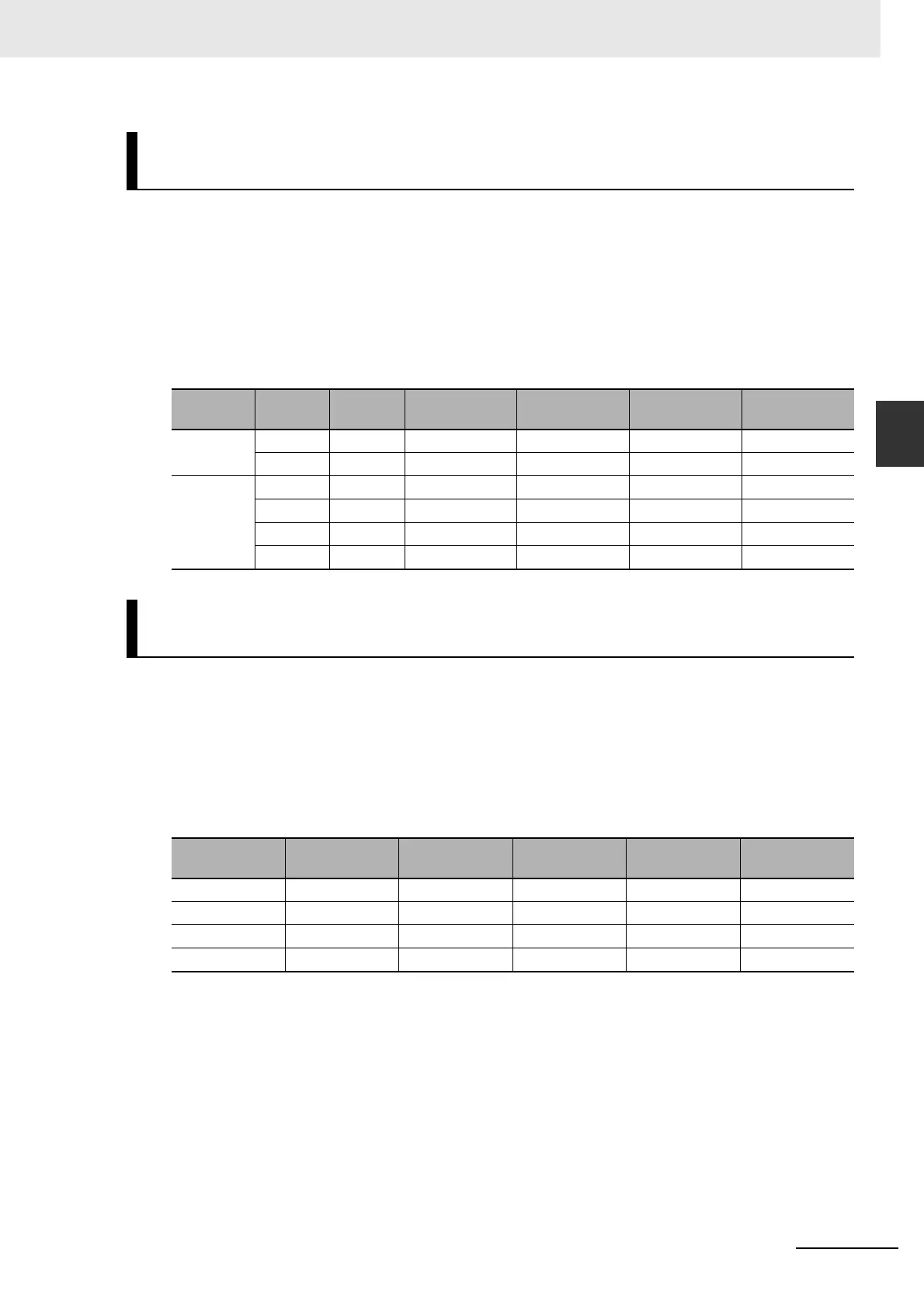
Pin 26: Damping Filter Switching 1 (DFSEL1)
No allocation: Damping Filter Switching 2 (DFSEL2)
This is the default allocation. The logic and allocation of input terminals (CN1 pin 1 to 8, 9, 26 to 33) can
be changed using Input Signal Selection 1 to 10 (Pn400 to Pn409).
Function
When Damping Filter Selection (Pn213) is set to 1 or 2, this signal enables the use of sequence
signals to switch among four damping control filters.
Pin 28: Electronic Gear Switching 1 (GESEL1)
No allocation: Electronic Gear Switching 2 (GESEL2)
This is the default allocation. The logic and allocation of input terminals (CN1 pin 1 to 8, 9, 26 to 33) can
be changed using Input Signal Selection 1 to 10 (Pn400 to Pn409).
Function
These two signals can be used to switch among up to four electronic gear ratio numerators.
Note Electronic Gear Ratio Denominator (Pn010) is common.
Damping Filter Switching 1 (DFSEL1) and Damping Filter
Switching 2 (DFSEL2)
Pn213 set
value
DFSEL1 DFSEL2
Damping Filter 1 Damping Filter 2 Damping Filter 3 Damping Filter 4
1 OFF – Enabled Enabled
ON – Enabled Enabled
2 OFF OFF Enabled
ON OFF Enabled
OFF ON Enabled
ON ON Enabled
Electronic Gear Switching 1 (GESEL1) and Electronic Gear
Switching 2 (GESEL2)
GESEL1 GESEL2
Electronic
Gear 1
Electronic
Gear 2
Electronic
Gear 3
Electronic
Gear 4
OFF OFF Pn009 enabled
ON OFF Pn500 enabled
OFF ON Pn501 enabled
ON ON Pn502 enabled

 Loading...


