3 - 63
3 Specifications
OMNUC G5-series (Pulse-train Input Type) AC Servomotors and Servo Drives User’s Manual
3-5 Cable and Connector Specifications
3
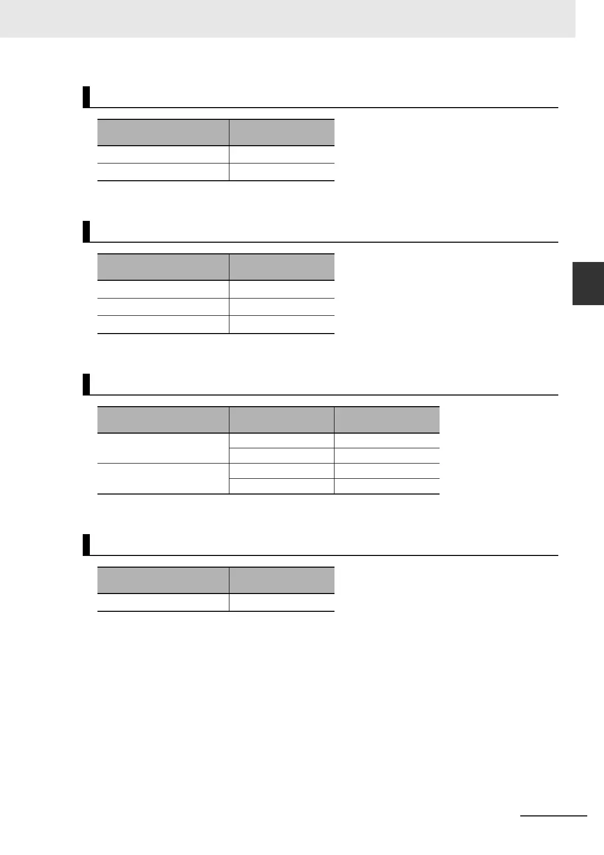
3-5-1 Resistance to Bending of Global Flexible Cable
*1 represents a number between 003 and 020.
*1 represents a number between 003 and 020.
*1 represents a number between 003 and 020.
*1 represents a number between 003 and 020.
Encoder Cables
Model
Minimum bending
radius (R)
R88A-CRGBCR
*1
45 mm
R88A-CRGCNR
*1
45 mm
Power Cables without Brake
Model
Minimum bending
radius (R)
R88A-CAGASR
*1
45 mm
R88A-CAGBSR
*1
90 mm
R88A-CAGDSR
*1
100 mm
Power Cables with Brake
Model Cable type
Minimum bending
radius (R)
R88A-CAGBBR
*1
Power cable 90 mm
Brake cable 45 mm
R88A-CAGDBR
*1
Power cable 100 mm
Brake cable 45 mm
Brake cable
Model
Minimum bending
radius (R)
R88A-CAGABR
*1
45 mm

 Loading...


