3 Specifications
3 - 86
OMNUC G5-series (Pulse-train Input Type) AC Servomotors and Servo Drives User’s Manual
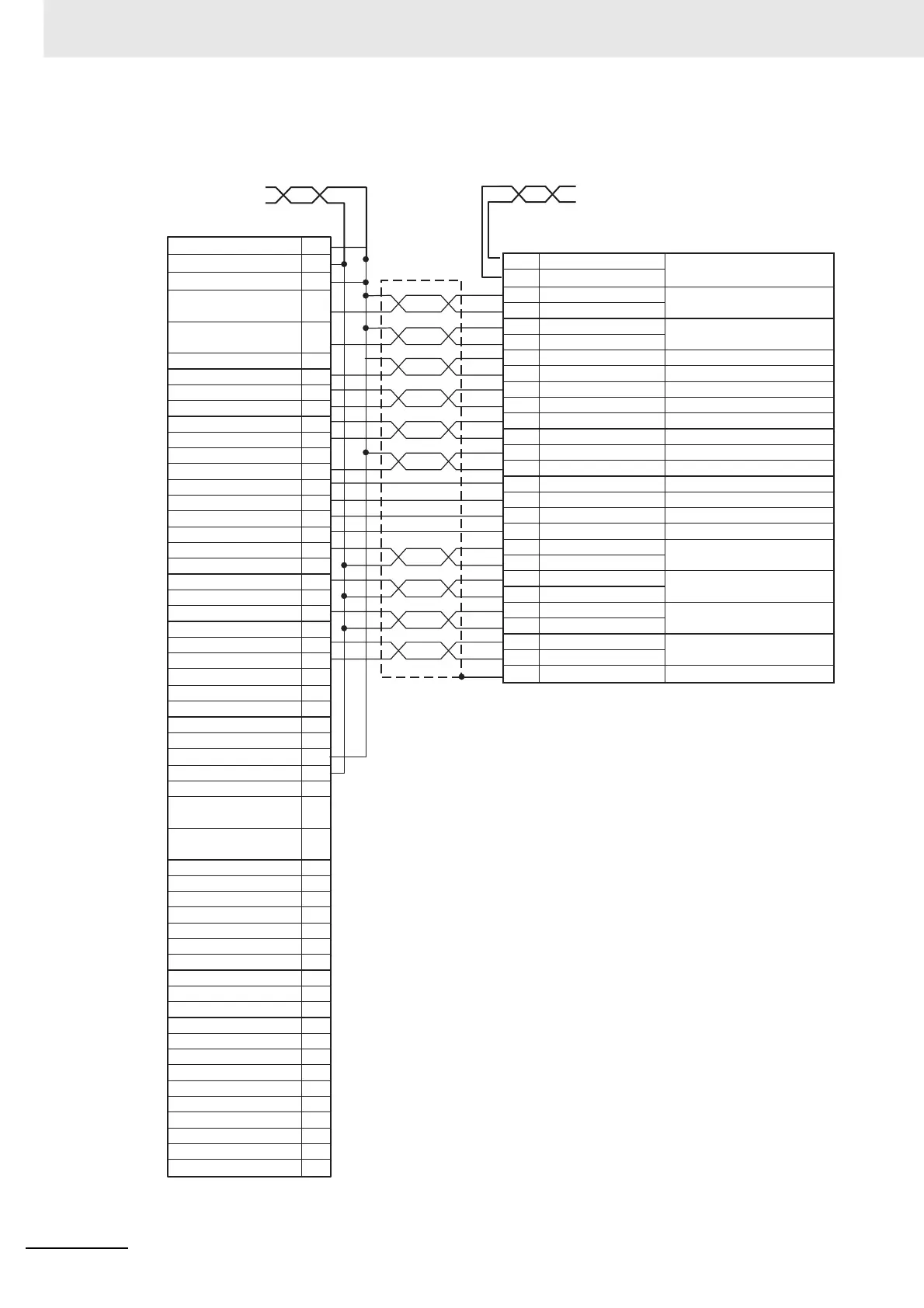
• Cables for Open Collector Output 1 Axis
1
3
5
16
18
21
20
23
22
25
24
15
11
10
12
13
7
6
9
26
27
2
4
50
38
36
35
34
33
32
31
30
41
45
44
42
43
49
48
47
29
28
11 BKIR
10 BKIRCOM
3 +CW/+PULS/+FA
4
–CW/–PULS/–FA
5
+CCW/+SIGN/+FB
6
–CCW/–SIGN/–FB
21 +A
22 –A
49 +B
48 –B
23 +Z
24 –Z
7 +24VIN
30 ECRST
29 RUN
26 DFSEL
31 RESET
27 TLSEL
39 INP
38 INPCOM
35 READY
34 REDYCOM
37 /ALM
36 ALMCOM
20 –
13 SGGND
Shell FG
AWG18 twisted-pair cable, 1 m
Red: 24 VDC
Black: 24 VDC GND
NC Unit side
XG4M-5030-T (OMRON)
24-V Power Supply for Output
24-V GND for Output
Input Common
Forward Direction Pulse Output
(with 1.6-kΩ resistor)
Reverse Direction Pulse Output
(with 1.6-kΩ resistor)
Forward Direction Pulse Output
(with 1.6-kΩ resistor)
Reverse Direction Pulse Output
(with 1.6-kΩ resistor)
Encoder Phase A +
Encoder Phase A –
Encoder Phase B +
Encoder Phase B –
Encoder Phase Z +
Encoder Phase Z –
Error Counter Reset Output
RUN Output
General-purpose Output
Alarm Reset Output
Torque Limit Output
Positioning Completion Input
General-purpose Input
Alarm Input
SEN Output
*2
Signal Ground
General-purpose Input
Alarm Input
SEN Output
*2
Signal Ground
24-V Power Supply for Output
24-V GND for Output
Input Common
Encoder Phase A +
Encoder Phase A –
Encoder Phase B +
Encoder Phase B –
Encoder Phase Z +
Encoder Phase Z –
Error Counter Reset Output
RUN Output
General-purpose Output
Alarm Reset Output
Torque Limit Output
Positioning Completion Input
Encoder Phase A + Output
Encoder Phase A – Output
Encoder Phase B + Output
Encoder Phase B – Output
Encoder Phase Z + Output
Encoder Phase Z – Output
+24-V Power Supply for Control
Error Counter Reset Input
Operation Command Input
Damping Filter Switching
Alarm Reset
Torque Limit Switching
Frame Ground
Brake Interlock
Output
Reverse Pulses,
Feed Pulses, or Phase A (*1)
Forward Pulse,
Direction Signal, or Phase B (*1)
Servo Ready
Completed Output
Alarm Output
Positioning Completion
Output 1
Sensor ON Input
AWG18 twisted-pair cable, 1 m
Blue: BKIRCOM
Black: BKIR
Servo Drive side (for Axis 1 or 3)
10150-3000PE (Sumitomo 3M)
*1 Connect the NC unit as shown here because it handles forward
direction commands as CW-direction/phase-A advance pulses
(which can be selected using the output pulse direction
selection parameter).
*2 G5-series Servo Drives (Pulse-train Input Type) support
incremental encoders only. Do not use SEN outputs.

 Loading...


