4 - 19
4 System Design
OMNUC G5-series (Pulse-train Input Type) AC Servomotors and Servo Drives User’s Manual
4-2 Wiring
4
4-2-2 Main Circuit and Motor Connections
On a Servo Drive with 2.0 kW or less, connector-type terminal blocks are used.
The procedure for wiring these terminal blocks is explained below.
1
Remove the terminal block from the Servo Drive before wiring.
The Servo Drive may be damaged if the wiring is done with the terminal block in place.
2
Strip off 8 to 9 mm of the covering from the end of each wire.
Refer to 4-2-2 Main Circuit and Motor Connections on page 4-14 for applicable wire sizes.
3
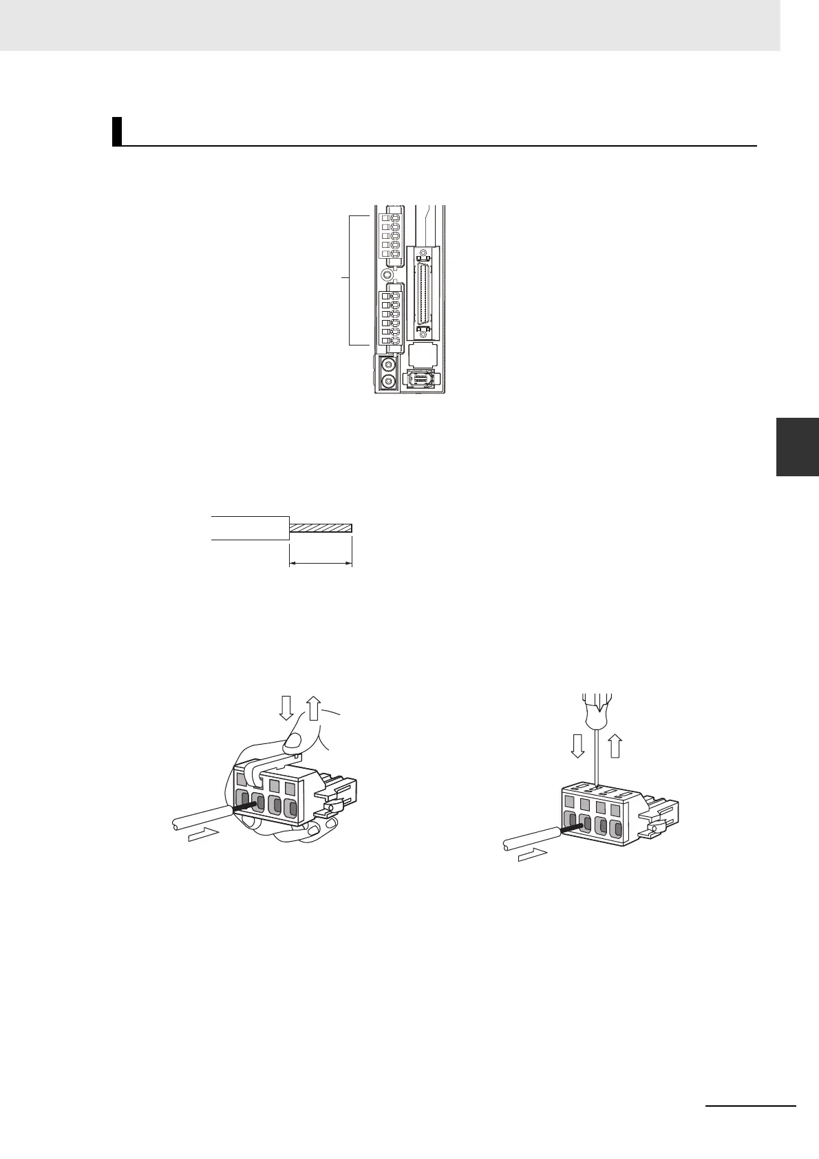
Open the wire insertion slots in the terminal block using a tool.
There are two ways to open the wire insertion slots, as follows.
• Pry the slot open using the lever that comes with the Servo Drive. (Figure A)
• Insert a flat-blade screwdriver (end width: 3.0 to 3.5 mm) into the opening for the driver on the
terminal block, and press down firmly to open the slot. (Figure B)
4
With the wire insertion slot held open, insert the end of the wire.
After inserting the wire, let the slot close by releasing the pressure from the lever or the
screwdriver.
5
Mount the terminal block to the Servo Drive.
After all of the terminals have been wired, return the terminal block to its original position on the
Servo Drive.
Note The wire may not be inserted easily depending on the shape of the ferrule connected to it.
If this occurs, perform one of the following methods before inserting the wire.
• Change the direction of inserting the connector by 90°.
• Correct the shape of the ferrule with pliers.
Terminal Block Wiring Procedure
Connector-type
terminal blocks
(Example: R88D-KP01H)
8 to 9 mm
Figure A
Figure B

 Loading...


