4 - 33
4 System Design
OMNUC G5-series (Pulse-train Input Type) AC Servomotors and Servo Drives User’s Manual
4-3 Wiring Conforming to EMC Directives
4
4-3-2 Selecting Connection Components
• Install surge suppressors for loads that have induction coils, such as relays, solenoids, brakes,
clutches, etc.
• The following table shows the types of surge suppressors and recommended products.
• Thyristors and varistors are made by the following manufacturers. Refer to manufacturer’s
documentation for details on these components.
Thyristors: Ishizuka Electronics Co.
Varistors: Ishizuka Electronics Co., Panasonic Corporation
• Select contactors based on the circuit’s inrush current and the maximum momentary phase current.
• The drive inrush current is covered in the preceding explanation of no-fuse breaker selection.
And the maximum momentary phase current is approximately twice the rated current.
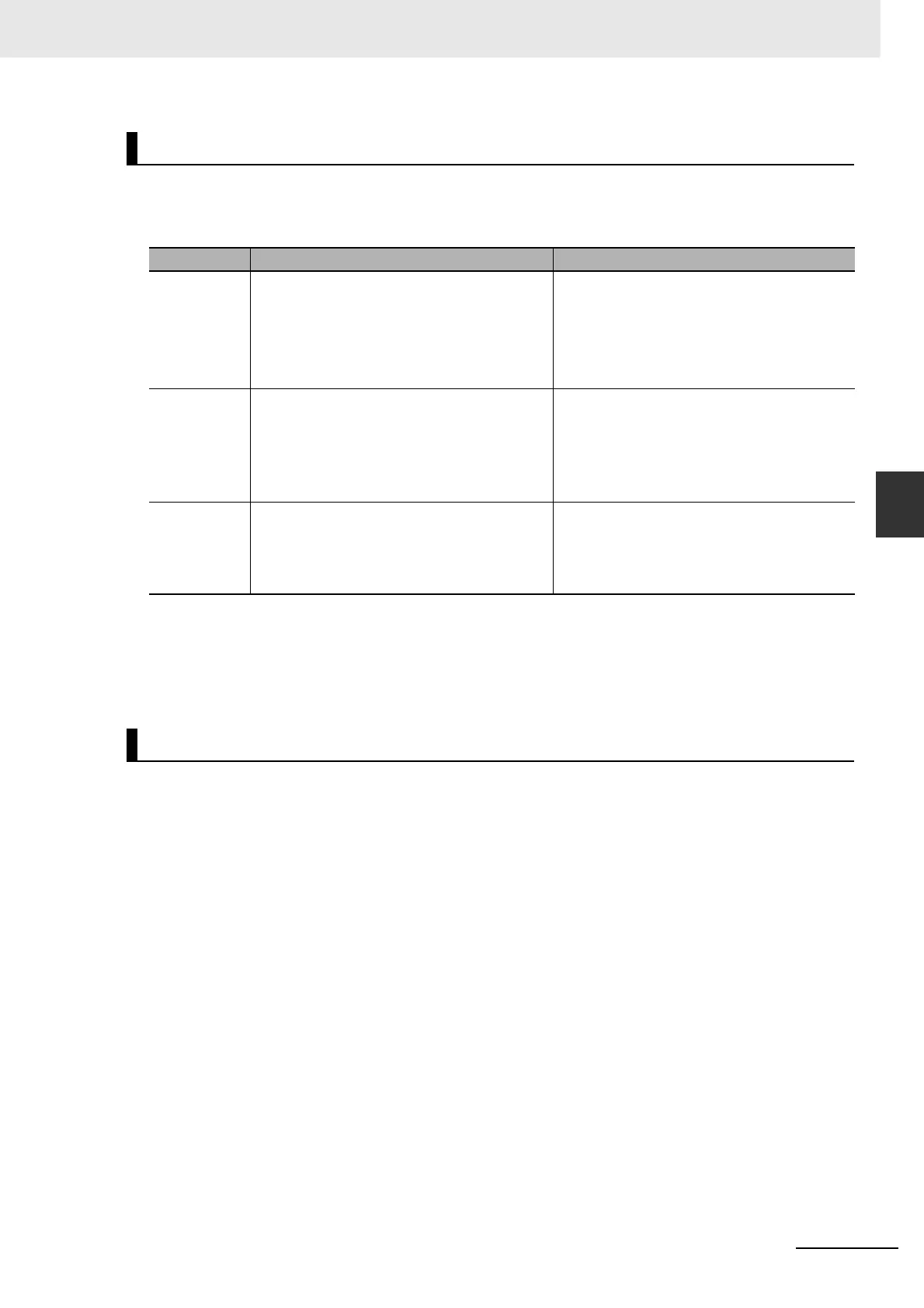
Surge Suppressors
Type Feature Recommended product
Diodes Diodes are used for relatively small loads such
as relays when the reset time is not a critical
issue.
At power shutoff the surge voltage is the
lowest, but the reset time takes longer.
Used for 24/48-VDC systems.
Use a fast-recovery diode with a short reverse
recovery time.
(e.g. RU2 of Sanken Electric Co., Ltd.)
Thyristors and
varistors
Thyristors and varistors are used for loads
when induction coils are large, as in
electromagnetic brakes, solenoids, etc., and
when reset time is critical.
The surge voltage at power shutoff is
approximately 1.5 times the varistor voltage.
Select the varistor voltage as follows.
200-VAC systems: varistor voltage 470 V
Capacitor
+ resistor
The capacitor plus resistor combination is used
to absorb vibration in the surge at power supply
shutoff. The reset time can be shortened by
selecting the appropriate capacitance and
resistance.
Okaya Electric Industries Co., Ltd.
XEB12002 0.2 µF - 120 Ω
XEB12003 0.3 µF - 120 Ω
Contactors

 Loading...


