EasyManuals Logo

Omron G5 Series User Manual

Omron G5 Series
506 pages
To Next Page IconTo Next Page
To Previous Page IconTo Previous Page
Page #299 background imageLoading...
Page #299 background image
6 - 17
6 Applied Functions
OMNUC G5-series (Pulse-train Input Type) AC Servomotors and Servo Drives User’s Manual
6-5 Encoder Dividing Function
6
6-5-2 Parameters Requiring Settings
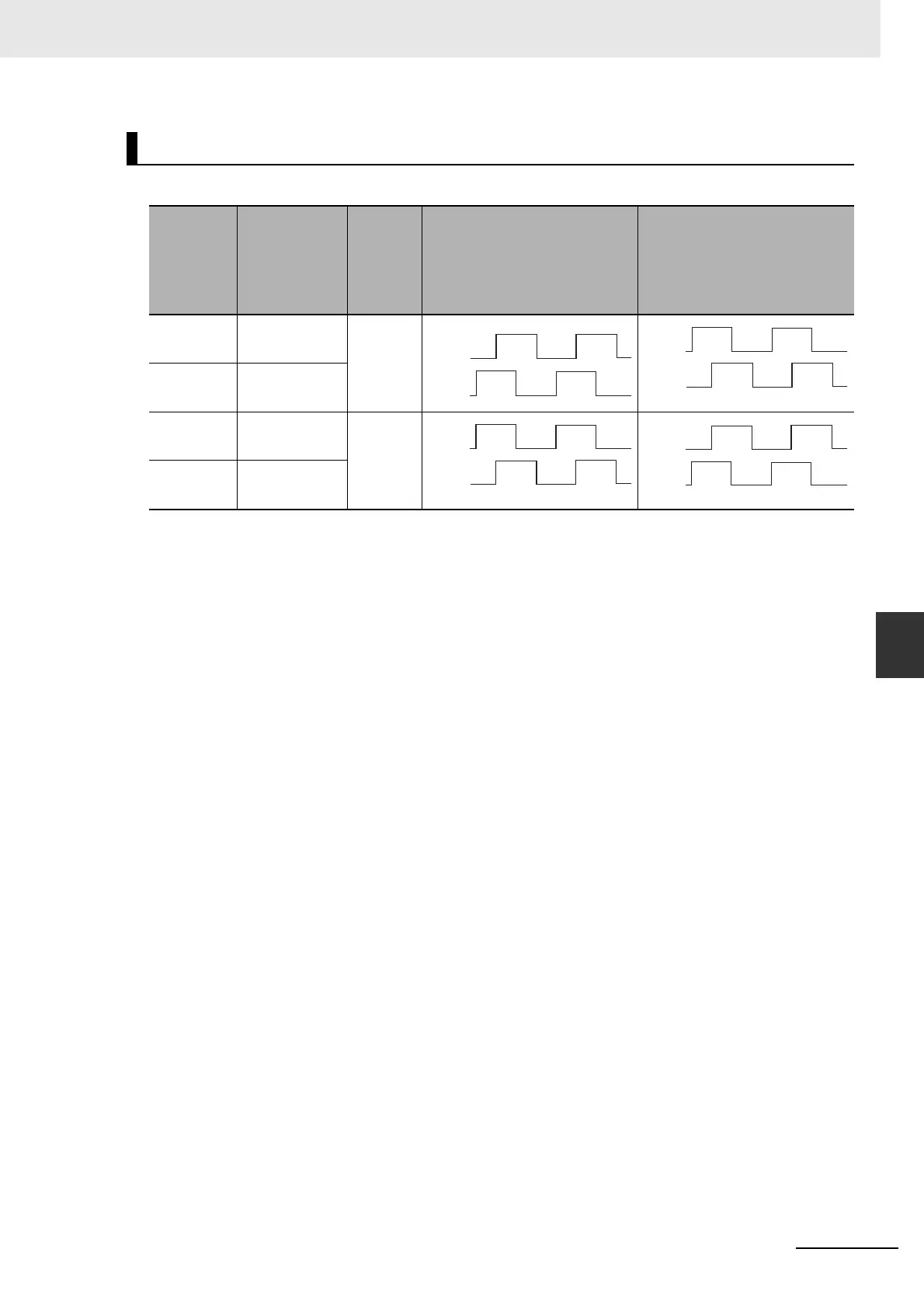
The scale corresponding to each output type is as follows.
Encoder Output Direction Switching Selection (Pn012)
Encoder
Output
Direction
Switching
Selection
(Pn012)
Output source
Phase-B
logic
When operating in forward
direction
When operating in reverse
direction
0 Encoder Non-
reverse
2 Reserved
(Do not set.)
1 Encoder Reverse
3 Reserved
(Do not set.)
Phase A
Phase B
Phase A
Phase B
Phase A
Phase B
Phase A
Phase B

Table of Contents

Other manuals for Omron G5 Series

Questions and Answers:

Question and Answer IconNeed help?

Do you have a question about the Omron G5 Series and is the answer not in the manual?

Omron G5 Series Specifications

General IconGeneral
FeedbackIncremental Encoder, Absolute Encoder
CommunicationEtherCAT
Safety FunctionSTO (Safe Torque Off)
Protection FunctionsOvervoltage, Undervoltage, Overcurrent
Vibration Resistance4.9 m/s² (10 to 55 Hz)

Related product manuals