6 - 37
6 Applied Functions
OMNUC G5-series (Pulse-train Input Type) AC Servomotors and Servo Drives User’s Manual
6-9 Sequence I/O Signals
6
6-9-3 Output Signals
Input the setting in each control mode to any of the parameters from Pn410 to Pn413 to allocate the signal.
The parameters must be set in hexadecimal notation, in the same method as for the input signal
allocations.
Set the set value of the function for each control mode in “**” below.
Refer to the function number table provided below for the set value of each function. The logic setting is
included in the function number.
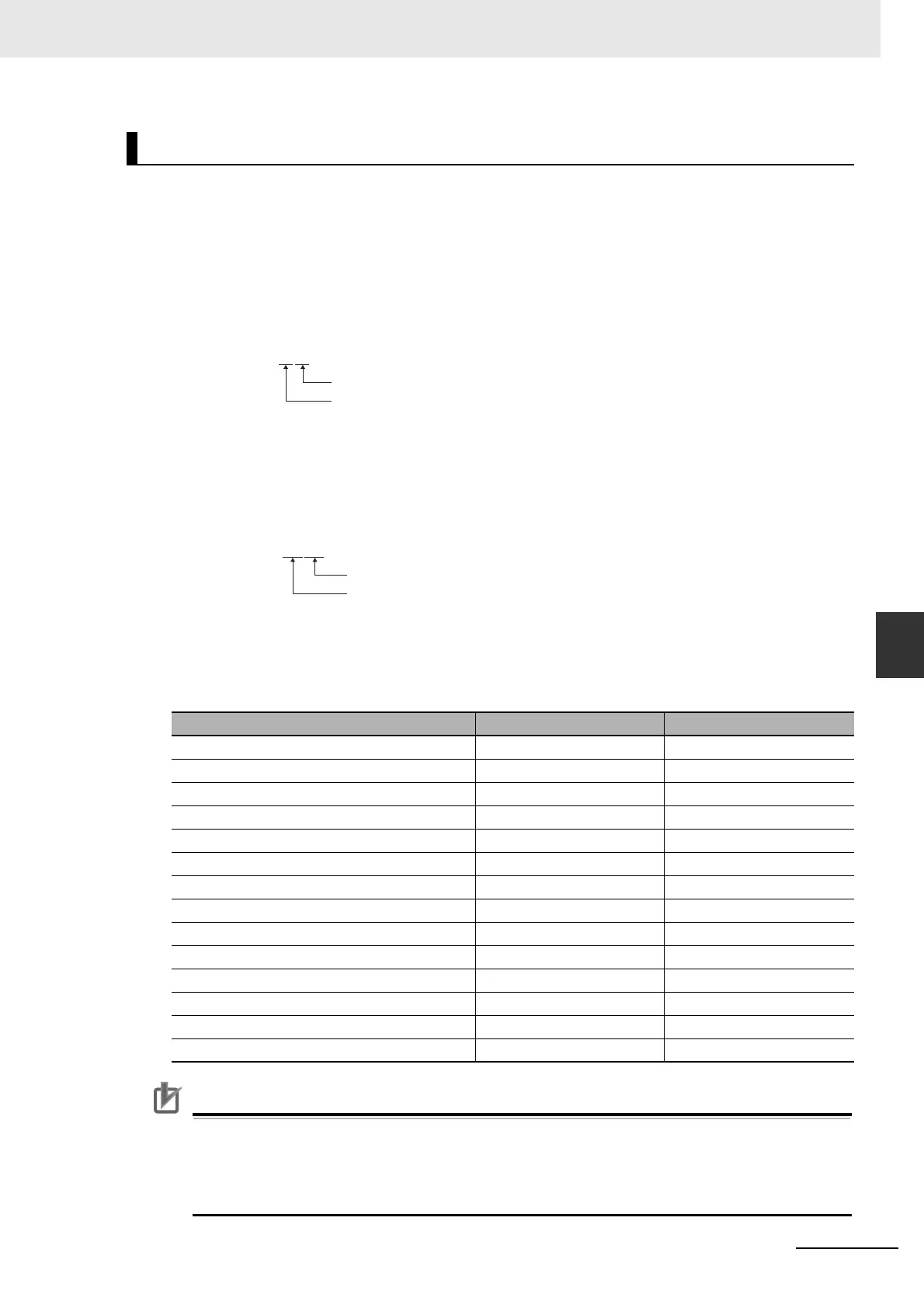
Example:
Position control: Speed Conformity Output Signal (08 hex)
Speed control: Motor Rotation Speed Detection Output (05 hex)
The set value on the front panel is indicated as a decimal, which is 1,288 in this case.
Function Number Table
The set values to be used for allocations are as follows:
Precautions for Correct UsePrecautions for Correct Use
• Do not use any values other than the settings listed.
• You can allocate the same function to more than one output signal.
• For output signals, the logic cannot be changed. The function is disabled (OFF) when signal
input is open with COM- and enabled (ON) when signal input is shorted with COM-.
Output Signal Allocation Method
Signal Symbol Set value
Disabled – 00 hex
Servo Ready Completed Output READY 02 hex
Brake Interlock Output BKIR 03 hex
Positioning Completion Output INP 04 hex
Motor Rotation Speed Detection Output TGON 05 hex
Torque Limiting Signal TLC 06 hex
Zero Speed Detection Signal ZSP 07 hex
Speed Conformity Output Signal VCMP 08 hex
Warning Output 1 WARN1 09 hex
Warning Output 2 WARN2 0A hex
Position Command Status Output P-CMD 0B hex
Positioning Completion Output 2 INP2 0C hex
Alarm Attribute Output ALM-ATB 0E hex
Speed Command Status Output V-CMD 0F hex
0000
****
h
Position control
Speed control
For parameters reserved for the system, do not change the values.
00000508h
Position control
Speed control

 Loading...


