7 Parameter Details
7 - 4
OMNUC G5-series (Pulse-train Input Type) AC Servomotors and Servo Drives User’s Manual
*1 The default setting is 11 for a Servo Drive with 200 V and 1 kW or more.
• Set the machine rigidity in 32 levels when realtime autotuning is enabled.
• Increasing or decreasing the set value too much at a time may cause the gain to change rapidly,
which applies an impact on the machine. Always start with a small value, and gradually increase it
while monitoring machine operation.
• Set the load inertia as a percentage of the motor rotor inertia.
• Pn004 = (Load inertia/Rotor inertia) x 100%
• When realtime autotuning is enabled, the inertia ratio is continuously estimated and saved to the
EEPROM every 30 minutes.
• When the inertia ratio is set correctly, the setting unit for Speed Loop Gain (Pn101) and Speed Loop
Gain 2 (Pn106) is Hz.
• If Inertia Ratio 1 (Pn004) is set larger than the actual value, the setting unit for speed loop gain is
larger. If Inertia Ratio 1 (Pn004) is set smaller than the actual value, the setting unit for speed loop
gain is smaller.
Explanation of Set Values
• Select whether to use photocoupler input or input for line driver only for command pulse input.
Explanation of Set Values
• Set the direction in which the Servomotor rotates in response to command pulse input.
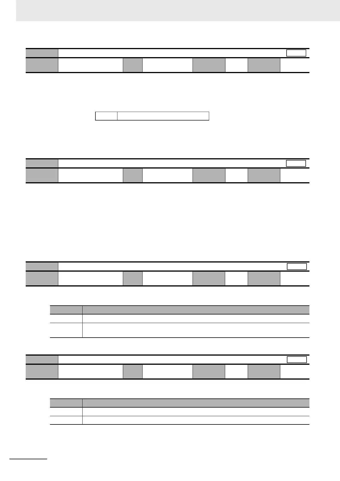
Pn003
Realtime Autotuning Machine Rigidity Setting
Setting
range
0 to 31 Unit – Default
setting
13
*1
Cycle the
power supply
–
Pn004
Inertia Ratio 1
Setting
range
0 to 10,000 Unit % Default
setting
250
Cycle the
power supply
–
Pn005
Command Pulse Input Selection
Setting
range
0 to 1 Unit – Default
setting
0
Cycle the
power supply
Required
Set value Description
0 Photocoupler input (+PULS: CN1 pin 3, –PULS: CN1 pin 4, +SIGN: CN1 pin 5, –SIGN: CN1 pin 6)
1 Input for line driver only (+CWLD: CN1 pin 44, –CWLD: CN1 pin 45, +CCWLD: CN1 pin 46,
–CCWLD: CN1 pin 47)
Pn006
Command Pulse Rotation Direction Switching Selection
Setting
range
0 to 1 Unit – Default
setting
0
Cycle the
power supply
Required
Set value Description
0 The Servomotor rotates according to the command pulse direction.
1 The Servomotor rotates opposite to the command pulse direction.
All
Low ← Machine rigidity → High
Low ← Servo gain → High
Low ← Responsiveness → High
0·1 - - - - - - - - - - - - - - - 31 Pn003
All
Position
Position
 Loading...


