7 - 5
7 Parameter Details
OMNUC G5-series (Pulse-train Input Type) AC Servomotors and Servo Drives User’s Manual
7-1 Basic Parameters
7
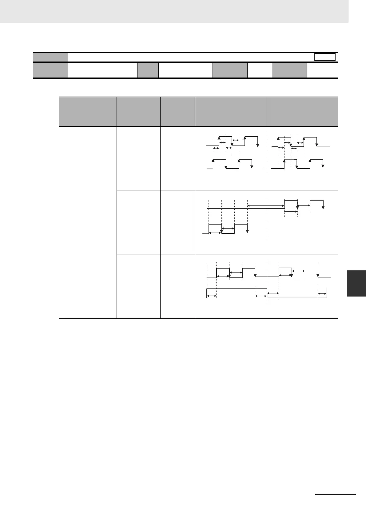
• Set the count method for the command pulse input.
Pn007
Command Pulse Mode Selection
Setting
range
0 to 3 Unit – Default
setting
1
Cycle the
power supply
Required
Command Pulse
Rotation Direction
Switching Selection
(Pn006)
Command
Pulse Mode
Selection
(Pn007)
Command
pulse
mode
Motor forward command Motor reverse command
0 0 or 2 90° phase
difference
(A/B) signal
input
Line driver: t1 ≥ 2 µs
Open collector: t1 ≥ 5 µs
1 Reverse
pulse/
Forward
pulse
Line driver: t2 ≥ 1 µs
Open collector: t2 ≥ 2.5 µs
3 Feed pulse/
Forward or
reverse
signal
Line driver: t2 ≥ 1 µs
Open collector: t2 ≥ 2.5 µs
Position
t1
t1
Phase
B
t1
t1
t1
Phase
t1
t1
t1
t2
t2
t2
t2
t3
t4
t4
t5
t5
t6
L
H
t6
t6
t6

 Loading...


