7 Parameter Details
7 - 6
OMNUC G5-series (Pulse-train Input Type) AC Servomotors and Servo Drives User’s Manual
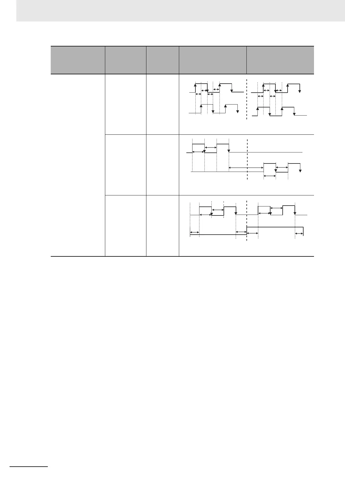
• Set the input pattern of the command pulses from the position controller to the Servo Drive.
1 0 or 2 90° phase
difference
(A/B) signal
input
Line driver: t1 ≥ 2 µs
Open collector: t1 ≥ 5 µs
1 Reverse
pulse/
Forward
pulse
Line driver: t2 ≥ 1 µs
Open collector: t2 ≥ 2.5 µs
3 Feed pulse/
Forward or
reverse
signal
Line driver: t2 ≥ 1 µs
Open collector: t2 ≥ 2.5 µs
Command Pulse
Rotation Direction
Switching Selection
(Pn006)
Command
Pulse Mode
Selection
(Pn007)
Command
pulse
mode
Motor forward command Motor reverse command
Phase
B
t1
t1t1
t1
t1
Phase
A
t1
t1
t1
t2
t2
t2
t2
t3
t4
t5
t4
t5
t6
t6
H
L
t6
t6

 Loading...


