7 - 7
7 Parameter Details
OMNUC G5-series (Pulse-train Input Type) AC Servomotors and Servo Drives User’s Manual
7-1 Basic Parameters
7
• Set the number of command pulses per motor rotation.
• When this parameter is set to 0, Electronic Gear Ratio Numerator 1 (Pn009) and Electronic Gear
Ratio Denominator (Pn010) are enabled.
• Set the electronic gear function.
• These parameters are enabled when Pn008 is set to 0.
• Intended use of the electronic gear function:
• Set the desired number of motor/Electronic Gear Ratio Denominator per unit number of input
command pulses.
• This parameter is used to increase the apparent command pulse frequency with the multiplication
function if the required motor speed cannot be obtained due to the limitation of the pulse
oscillation capacity (i.e., maximum allowable output frequency) of the host system.
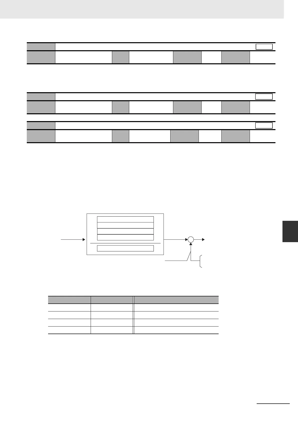
• Block diagram of the electronic gear function:
*1 The selection of second to fourth numerators is made based on the Electronic Gear Switching 1 and 2
(GESEL1 and GESEL2) settings.
Although Pn008, Pn009, and Pn010 can be set to any value within the setting range, OMRON will not
guarantee that the function operates as intended with any extreme electronic gear ratio setting. It is
recommended that the electronic gear ratio be used between 1/1,000 and 1,000.
For the setting method, refer also to
6-4 Electronic Gear Function on page 6-11.
Pn008
Electronic Gear Integer Setting
Setting
range
0 to 2
20
Unit pulses Default
setting
10,000
Cycle the
power supply
Required
Pn009
Electronic Gear Ratio Numerator 1
Setting
range
0 to 2
30
Unit – Default
setting
0
Cycle the
power supply
–
Pn010
Electronic Gear Ratio Denominator
Setting
range
1 to 2
30
Unit – Default
setting
10,000
Cycle the
power supply
–
GESEL1 GESEL2 Selected numerator
OFF OFF Electronic Gear Ratio Numerator 1
ON OFF Electronic Gear Ratio Numerator 2
OFF ON Electronic Gear Ratio Numerator 3
ON ON Electronic Gear Ratio Numerator 4
Position
Position
Position
Command
pulse
*1
*1
*1
Internal
command
F
f
+
–
Feedback
pulse
(resolution)
To error counte
10,000 P/rev
or
2 P/rev
Denominator (Pn010)
Numerator 1 (Pn009)
Numerator 2 (Pn500)
Numerator 3 (Pn501)
Numerator 4 (Pn502)
17
 Loading...


