7 Parameter Details
7 - 8
OMNUC G5-series (Pulse-train Input Type) AC Servomotors and Servo Drives User’s Manual
• When Encoder Dividing Denominator (Pn503) is set to 0, the encoder resolution is used as the
denominator for dividing the pulse output.
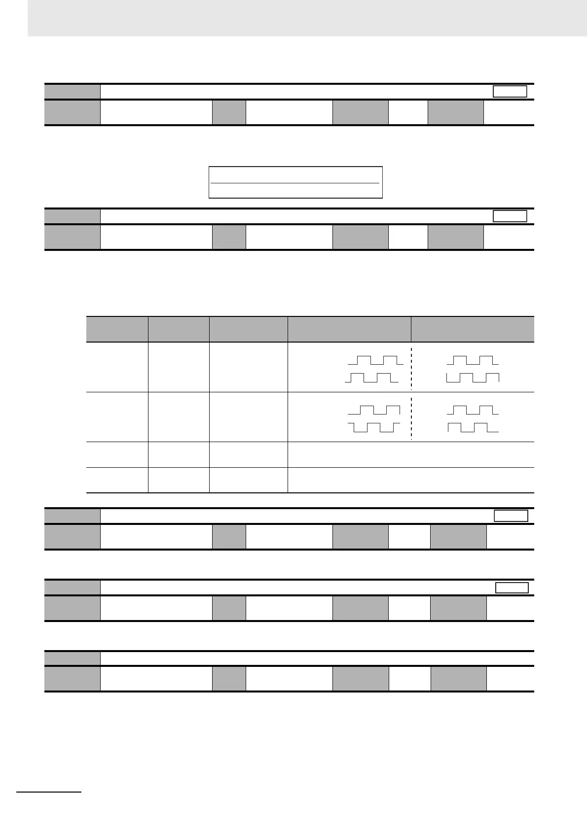
• Select the combination of the phase-B logic and the output source for pulse output.
Select Encoder as the output source.
Explanation of Set Values
• Set the first output torque limit of the Servomotor.
• Set the range of the error counter overflow level.
• Do not set.
Pn011
Encoder Dividing Numerator
Setting
range
1 to 262,144 Unit P/r Default
setting
2,500
Cycle the
power supply
Required
Pn012
Encoder Output Direction Switching Selection
Setting
range
0 to 1 Unit – Default
setting
0
Cycle the
power supply
Required
Set value
Phase-B
logic
Output source Motor forward command Motor reverse command
0 Not reversed Encoder
1 Reversed Encoder
2
Reserved
––
3
Reserved
––
Pn013
No. 1 Torque Limit
Setting
range
0 to 500 Unit % Default
setting
500
Cycle the
power supply
–
Pn014
Error Counter Overflow Level
Setting
range
0 to 2
27
Unit Command units Default
setting
100,000
Cycle the
power supply
–
Pn015 Reserved
Setting
range
1 Unit – Default
setting
1
Cycle the
power supply
–
All
Pn011 x 4 (if host system uses quadruple process)
Encoder resolution
Encoder pulse → → Output pulse
All
Phase A
Phase B
Phase A
Phase B
Phase A
Phase B
Phase A
Phase B
All
Position
 Loading...


