10 Troubleshooting and Maintenance
10 - 14
OMNUC G5-series (Pulse-train Input Type) AC Servomotors and Servo Drives User’s Manual
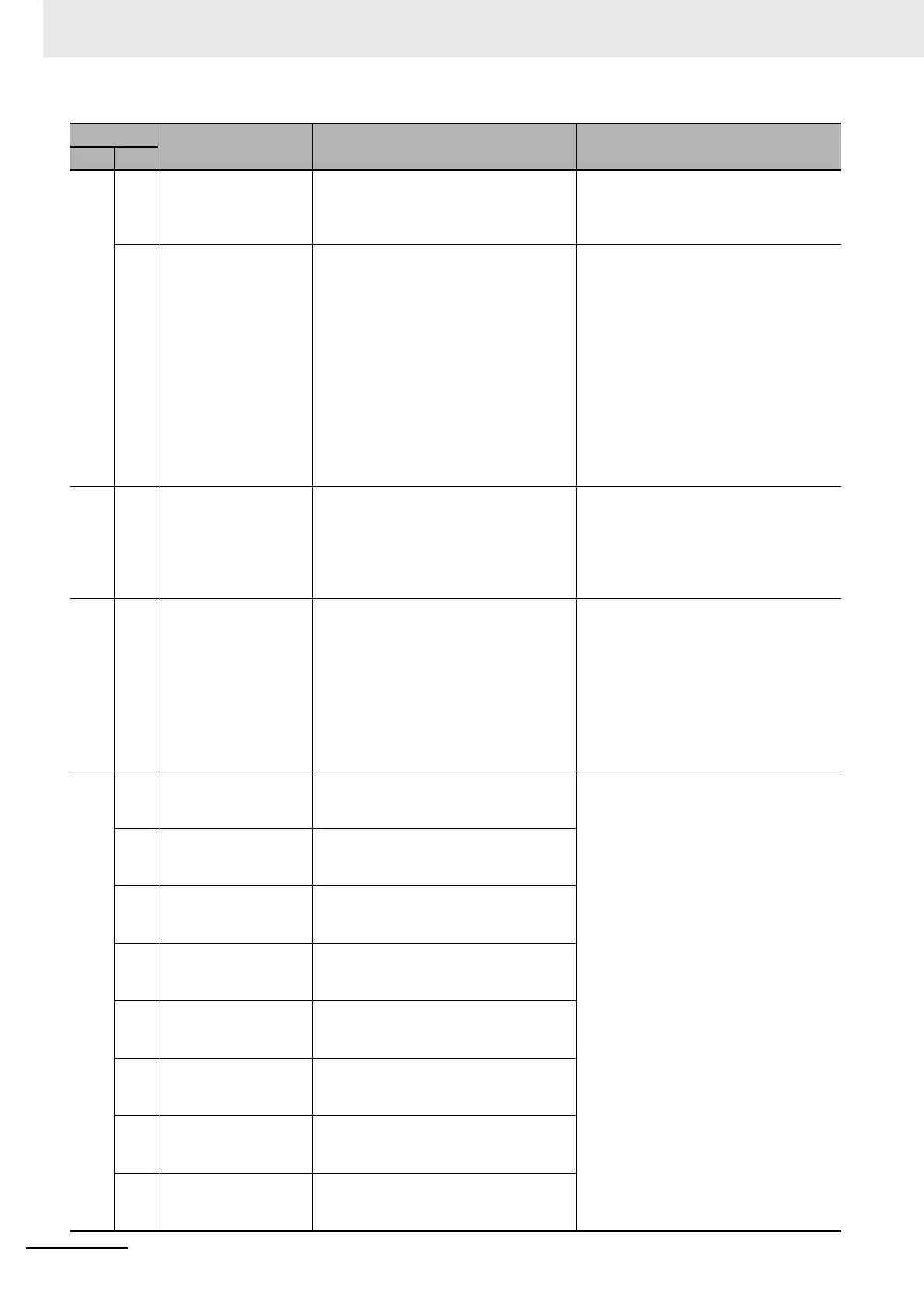
27 0 Command Pulse
Frequency Error
The command pulse input frequency
exceeded the value set in Command
Pulse Input Maximum Setting (Pn532) x
1.2.
Check the command pulse input.
2 Command Pulse
Multiplier Error
The parameter setting for the command
pulse frequency or the electronic gear
ratio is not appropriate.
The value obtained by multiplying the
number of command pulses per 0.167
ms by the electronic gear ratio exceeded
approximately 3 Gpps (approximately
175 kpps for software versions earlier
than V1.10).
The command pulse input is sparse or
dense.
There is an erroneous count due to noise
contained in the command pulse input.
• Set the electronic gear ratio as small
as possible in the range of 1/1,000 to
1,000 times.
• Check the command pulse input.
• Use the line driver interface if possible.
• Set Command Pulse Input Maximum
Setting (Pn532) to less than 1,000 and
enable the digital filter.
28 0 Pulse Regeneration
Error
The pulse regeneration output frequency
exceeded the allowable limit.
• Check the values set in Encoder
Dividing Numerator (Pn011) and
Encoder Dividing Denominator
(Pn503).
•
To disable the detection, set Pulse
Regeneration Limit Setting (Pn533) to 0.
29 0 Error Counter
Overflow
The position error counter value
obtained with reference to the encoder
pulses exceeded +2
29
(536,870,912).
• Check to see if the Servomotor rotates
according to the position command.
• Check with the torque monitor to see if
the output torque is saturated.
• Adjust the gain.
• Maximize the values set in No.1
Torque Limit value (Pn013) and No.2
Torque Limit value (Pn522).
• Wire the encoder cable correctly.
33 0 Interface Input
Duplicate Allocation
Error 1
There is a duplicate setting in the input
signal (IN1, IN2 IN3, IN4, or IN5)
function allocations.
Make sure that functions are correctly
allocated to these connector pins.
1 Interface Input
Duplicate Allocation
Error 2
There is a duplicate setting in the input
signal (IN6, IN7, IN8, IN9, or IN10)
function allocations.
2 Interface Input
Function Number Error
1
There is an undefined number
specification in the input signal (IN1, IN2,
IN3, IN4, or IN5) function allocations.
3 Interface Input
Function Number Error
2
There is an undefined number
specification in the input signal (IN6, IN7,
IN8, IN9, or IN10) function allocations.
4 Interface Output
Function Number Error
1
There is an undefined number
specification in the output signal (SO1 or
SO2) function allocation.
5 Interface Output
Function Number Error
2
There is an undefined number
specification in the output signal (SO4)
function allocation.
6 Counter Reset
Allocation Error
The Error Counter Reset Input (ECRST)
pin was allocated to other than the input
signal S17.
7 Command Pulse
Prohibition Input
Allocation Error
The Pulse Prohibition Input (IPG)
function was allocated to other than the
input signal SI10.
Alarm No.
Name Cause Measures
Main
Sub

 Loading...


