A - 3
Appendices
OMNUC G5-series (Pulse-train Input Type) AC Servomotors and Servo Drives User’s Manual
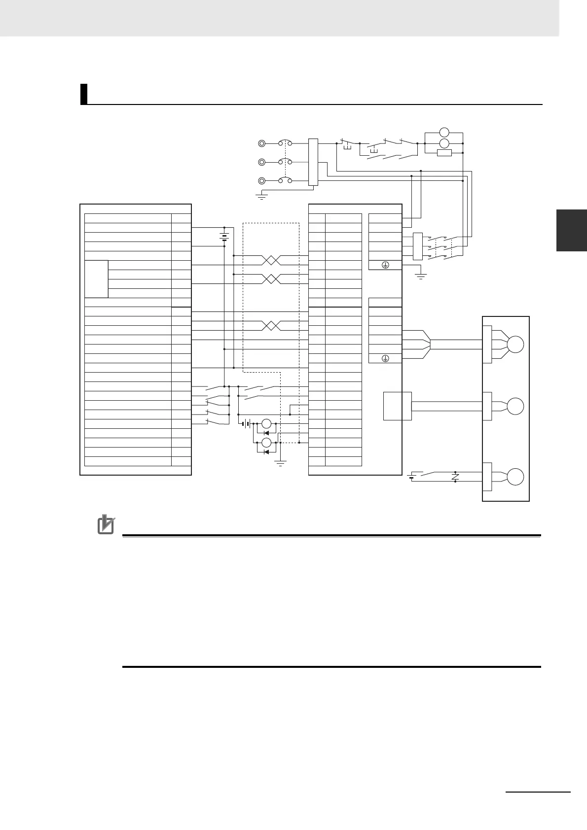
A-1 Connection Examples
A
Precautions for Correct UsePrecautions for Correct Use
• The above example shows an example of connecting a Servo Drive with 3-phase 200 VAC
main circuit power supply inputs. Use a power supply and power cables that meet the power
supply specifications of the Servo Drive.
• Note that incorrect connection of signal lines may cause damage to the Servo Drive and
connected units.
• Leave unused signal wires disconnected and open.
• Use mode 2 for origin search.
• Recommended surge-absorbing diode: RU2 (Sanken Electric Co., Ltd.) or equivalent
• Connect signal lines so that the servo can be turned ON and OFF with the RUN signal.
Example 2: Connection with SYSMAC CJ1W-NC113/213/413
No.
CN1 CNA
CNB
A1
A2
6
3
4
30
23
24
39
7
29
31
38
36
5
L1C
L2C
L1
L2
L3
B1
B3
B2
U
V
W
INP
RUN
RESET
INPCOM
ALMCOM
FG
A8
A7
A6
A5
A9
A14
A12
A11
A20
A15
A17
A19
A18
A16
24 VDC
ECRST
CJ1W-NC113/213/413
R88D-KP
X1
24 VDC
XB
BKIRCOM
10
BKIR
11
37
/ALM
M
R88M-KE
CN2
E
24 VDC
B
XB
R
S
T
MC1
NFB
ONOFF
X1MC1
Main Circuit Power Supply
Reactor
Description
24-V Power Supply for Output
0 V Power Supply for Output
MC2
MC1 MC2
SUP
MC2
MC1
X1
MC2
Red
White
Blue
Green/
Yellow
Motor
Power Cable
Encoder Cable
Brake Cable
3-phase 200 to 240 VAC 50/60 Hz
Noise Filter
Shell
Main Circuit
Contactor
Surge Suppresso
+CCW
+CW
–CCW
–CW
+Z
+24VIN
–Z
X-axis Origin Common
X-axis Positioning Completion Input
Input Common
X-axis External Interrupt Input
X-axis Origin Proximity Input
X-axis CCW Limit Input
X-axis CW Limit Input
X-axis Immediate Stop Input
X-axis Error Counter Reset Output
X-axis Origin Line Driver Input
Ground to
100 Ω or Less
CCW (With resistance)
CCW (Without resistance)
CW (With resistance)
CW (Without resistance)
X-axis
Pulse
Output

 Loading...


