A - 7
Appendices
OMNUC G5-series (Pulse-train Input Type) AC Servomotors and Servo Drives User’s Manual
A-1 Connection Examples
A
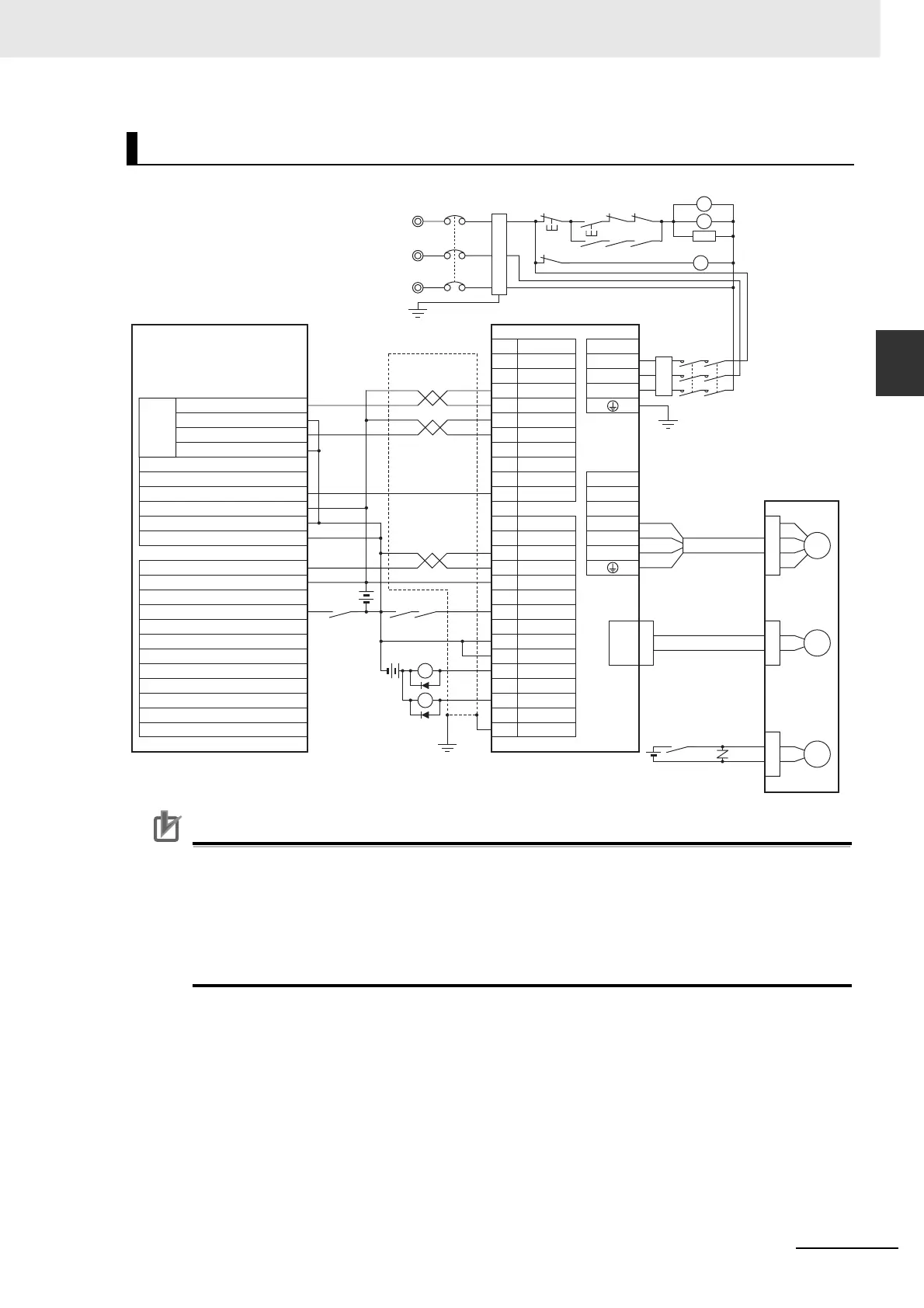
Precautions for Correct UsePrecautions for Correct Use
• Note that incorrect connection of signal lines may cause damage to the Servo Drive and
connected units.
• Leave unused signal wires disconnected and open.
• Use a separate power supply (24 VDC) for the brake, independent of the 24 VDC control
power supply.
• Recommended surge-absorbing diode: RU2 (Sanken Electric Co., Ltd.) or equivalent
Example 6: Connection with SYSMAC CP1H-X
DT-D/CP1L-
DT-D
S
CN1 CNA
4
2
6
30
7
29
37
11
1
L1
L2
U
V
W
RUN
36 ALMCOM
/ALM
FG
X1
XB
24 VDC
R
T
NFB
ONOFF
X1
MC1
X1
24 VDC
BKIR
SGGND
25
SGGND
17
MC1
X1
L3
M
CN2
E
24 VDC
B
XB
PL
BKIRCOM
10
MC2
SUP
MC2
MC1
MC2
MC1MC2
Reactor
CP1H-X40DT-D R88-KP
Output Terminal Block
Origin Search 0 (word 101, bit 02)
24 VDC Input Terminal (
+
)
COM (for word 101, bit 00 to 03)
Input Terminal Block
Shell
+24VCW
–CW
+24VCCW
–CCW
ECRST
+24VIN
Pulse
Output
0
24 VDC Input Terminal (–)
Pulse 0 Origin Input Signal (word 0, bit 00)
COM0CH
Pulse 0 Origin Proximity Input Signal (word 0, bit 01)
CNB
B1
B3
B2
R88M-KE
Servo Error Display
Main Circuit Power Supply
Main Circuit
Contactor
Surge Suppressor
Noise Filter
Ground to
100 Ω or Less
Red
White
Blue
Green/
Yellow
Motor
Power Cable
Encoder Cable
Brake Cable
CW0 (word 100, bit 00)
COM (for word 100, bit 00)
CCW0 (word 100, bit 01)
COM (for word 100, bit 01)

 Loading...


