A - 9
Appendices
OMNUC G5-series (Pulse-train Input Type) AC Servomotors and Servo Drives User’s Manual
A-1 Connection Examples
A
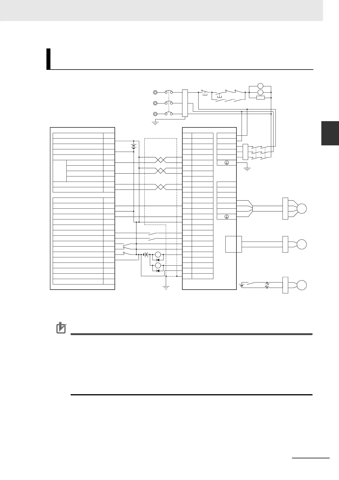
*1 The I/O signals for the HCP22 vary depending on the allocations of internal relay areas. Change the wiring
according to the allocations.
Precautions for Correct UsePrecautions for Correct Use
• Note that incorrect connection of signal lines may cause damage to the Servo Drive and
connected units.
• Leave unused signal wires disconnected and open.
• Use a dedicated power supply (24 VDC) for the command pulse power.
• Recommended surge-absorbing diode: RU2 (Sanken Electric Co., Ltd.) or equivalent
• Use a separate power supply (24 VDC) for the brake, independent of the 24 VDC control
power supply.
Example 8: Connection with SYSMAC Customizable Counter Unit
CS1W-HCP22-V1
CS1W-HCP22-V1 R88D-KP
Description
No.
CN1
Special I/O Connector
I/O Connector
CNA
CNB
24 VDC Power Supply for Output
Error Counter Clear*1
A19
Common
CCW (1.6kΩ)
CW (1.6kΩ)
Z Phase LD+
Z Phase LD–
24 V for Output
Positioning Completion Signal *1
Output Common
Servo ON *1
Alarm Reset*1
Origin Proximity Input Signal *1
CCW Limit Input Signal*1
CW Limit Input Signal*1
Input Common*1
A20
6
3
4
23
24
30
7
29
31
39
36
Shell
5
+CCW
L1C
L2C
L1
L2
L3
B1
B2
U
V
W
–
CCW
+CW
–
CW
+Z
–Z
ECRST
+
24VIN
28
INPCOM
RUN
RESET
INP
ALMCOM
FG
A18
A16
B5
B3
B1
A5
A1
A10
B7
B5
B4
B12
B8
B9
Pulse
Output
1
37
/ALM
X1
24 VDC
X1
24
VDC
B3
XB
BKIRCOM
10
BKIR
11
M
R88M-KE
CN2
E
24 VDC
B
XB
R
S
T
MC1
NFB
ONOFF
X1MC1
Reactor
SUP
MC2
MC1
MC2
MC1 MC2
MC2
3-phase 200 to 240 VAC 50/60 Hz
Main Circuit Power Supply
Main Circuit
Contactor
Surge Suppresso
Noise Filter
Ground to
100 Ω or Less
Red
White
Blue
Green/
Yellow
Motor
Power Cable
Encoder Cable
Brake Cable

 Loading...


