2 - 35
2 Models and External Dimensions
OMNUC G5-series (Pulse-train Input Type) AC Servomotors and Servo Drives User’s Manual
2-4 External and Mounting Dimensions
2
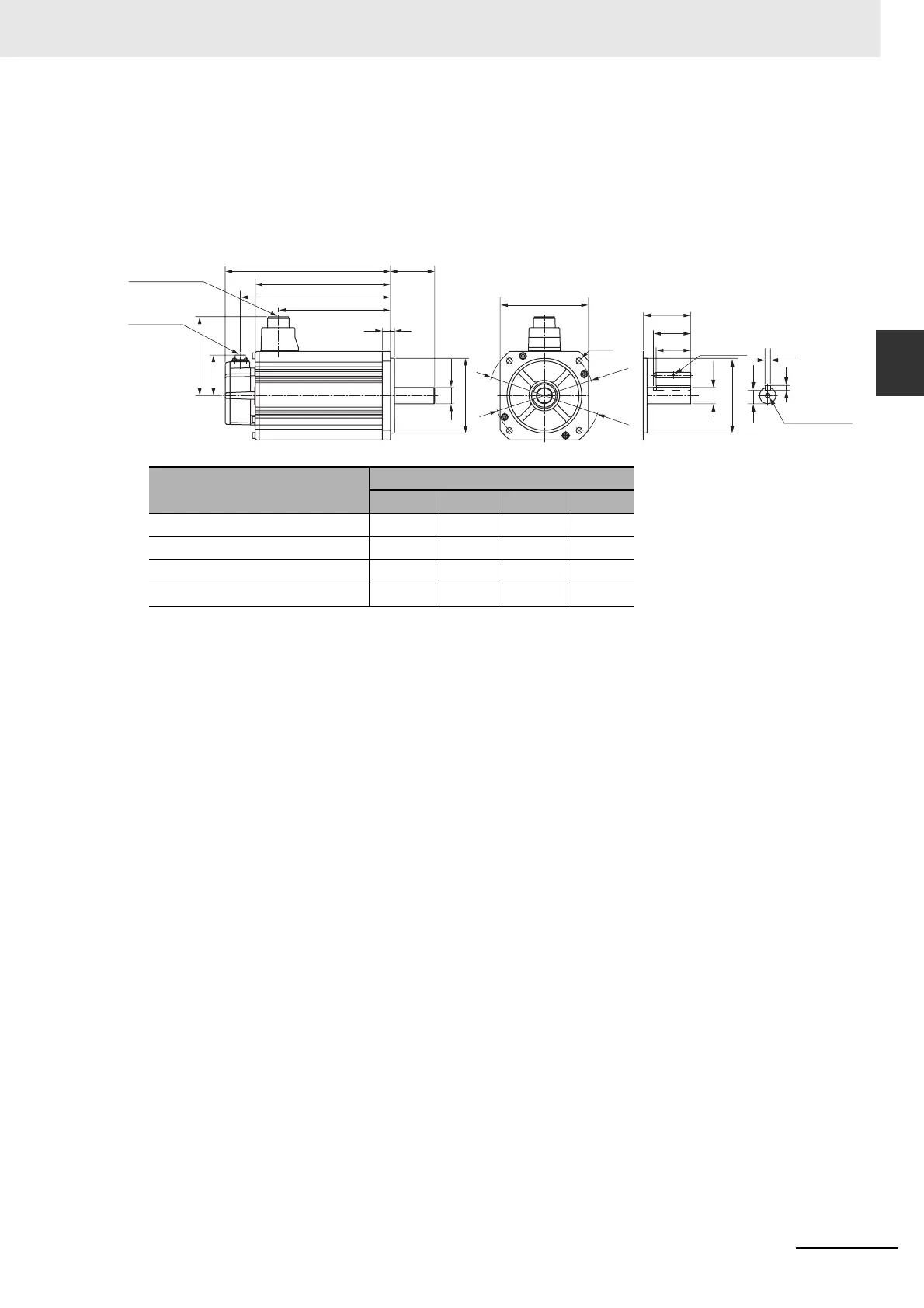
2-4-2 Servomotor Dimensions
4 kW/5 kW (without Brake)
R88M-KE4K030H (-S2)/-KE5K030H (-S2)
4 kW/5 kW (with Brake)
R88M-KE4K030H-B (S2)/-KE5K030H-B (S2)
Note The standard models have a straight shaft. Models with a key and tap are indicated with S2 at the end of the
model number.
Models with an oil seal are indicated with O at the end of the model number. The motor dimensions do not
change.
Model
Dimensions [mm]
LL LM KB1 KB2
R88M-KE4K030 209 164 127 189
R88M-KE5K030 244 199 162 224
R88M-KE4K030-B 237 192 127 217
R88M-KE5K030-B 272 227 162 252
Encoder
connector
Motor and brake
connector
LM
KB2
KB1
65LL
118
84
612
ø24h6
ø110h7
130
4-ø9
ø165
ø145
51
55
65
M3, through
M8 depth 20
ø24h6
ø110h7
8h9
7
20
(Shaft end specifications
with key and tap)

 Loading...


