126
Ethernet Communications Section 7-3
7-3-2 Application Example
System Configuration
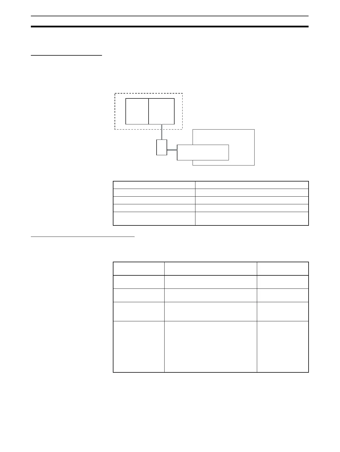
This section uses the following example to describe how to access the G9SP-
series Controller from a Standard PLC by performing Ethernet communica-
tions through an Ethernet Communications Board (CP1W-CIF41).
Note This example uses the following OMRON Standard PLC.
G9SP-series Controller Settings
Make the settings for TCP/IP in the system settings of the G9SP Configurator.
These settings are set in the G9SP-series Controller and Ethernet Option
Board when the configuration data is downloaded.
Product Model/version
CPU Unit (Standard PLC) CJ1M-CPU11
Ethernet Communications Unit CJ1W-ETN21
Switching hub W4S1-05B
Support Software (for setup and
creating ladder programs)
CX-Programmer Ver. 9.10
CJ1M
CJ1W-ETN21
Ethernet Unit
G9SP-series Controller
FINS/UDP
OMRON Standard PLC (See note.)
CP1W-CIF41
Option Board
192.168.250.1
192.168.250.2
Switching hub
Parameter Description Set value for this
example
IP address IP address of Ethernet Option Board.
Default value: 192.168.250.1
192.168.250.2
Subnet mask Subnet mask of Ethernet Option Board.
Default value: 255.255.255.0
No change is
required.
Default gateway Set the IP address of the default gate-
way. Default value: 0.0.0.0 (IP routing
not supported)
No change is
required.
FINS node address Set the FINS node address of the
Ethernet Option Board. If automatic
setting is specified, a value that
matches the rightmost byte of the IP
address is stored.
Default value: Automatic (matching the
rightmost byte of the IP address)
Setting range: 1 to 254
No change is
required.

 Loading...


