102 LD-250 Platform User's Guide 20472-000 Rev B
6.2 Payload Bay Connections - LD-250 Core
Nominal Qty Actual
Maximum
Current
Description
5 VDC 1 5 VDC±5% 1 A Switched Aux power
12 VDC 1 12 VDC±5% 1 A Switched Aux power
20 VDC 1 20 VDC±5% 1 A Switched Aux power
22 - 30 VDC 2 battery 4 A Switched
22 - 30 VDC 1* battery 10 A Switched
22 - 30 VDC 1* battery 10 A Safe, Switched
* 10 A Switched and 10 ASafe, Switched share the 10 A of current.
Each supply has an associated LED which, when lit, indicates that the port is actively
powered. See LD-250 Core Status Indicators on page 132.
When you press an E-Stop button (or if a the rear sensor or a user bumper contacts an
obstacle), it disconnects the Safe 22 - 30 VDC.
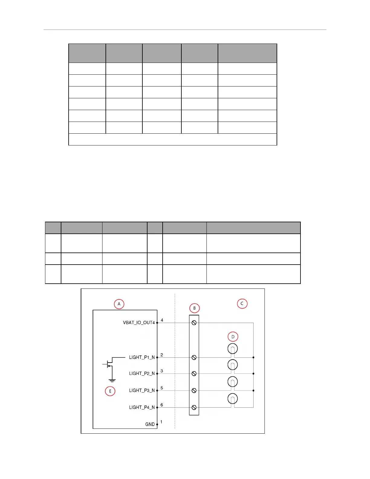
LIGHTS (Light Pole)
The LD-250 Core's light pole Mini-Fit
®
2 x 3 connector enables you to connect a light pole or
other payload warning lights.
Pin Designation Notes Pin Designation Notes
1 GND Cable shield 4 VBAT_IO_
OUT4
VBAT @ 0.5A Max (shared with
DIO)
2 LIGHT_P1 Red 5 LIGHT_P3 Green
3 LIGHT_P2 Yellow or
orange
6 LIGHT_P4 Buzzer