134 LD-250 Platform User's Guide 20472-000 Rev B
7.6 Sensors
If the LD-250 must operate close to reflective objects, Omron recommends that you use a com-
bination of markings on the objects, such as highly visible tape or painted stripes. In addition,
specify forbidden sectors in the workspace map so that the LD-250 can plan paths to avoid
these objects.
Low Front Laser
The low front laser [(B) in Figure 7-8] detects obstacles below the scanning plane of the safety
laser, such as an empty pallet or a human foot. This laser also detects obstacles that might be
significantly wider at the base, such as a column plinth, where the main safety laser might
detect only the upper portion of the column.
Rear Sensor
The LD-250 includes a rear-facing sensor that detects obstacles that are close to the rear, such
as person stepping behind the LD-250. The sensor also detects obstacles that the AMR might
encounter when reversing or rotating.
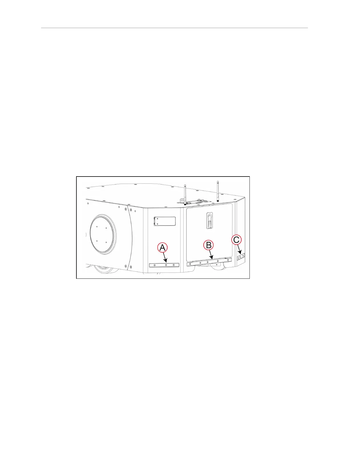
The LD-250's rear sensor consists of an array of individual time-of-flight sensors in three seg-
ments (right, left and center) as shown in Figure 7-9.
Figure 7-9 Rear Sensor: Left (A), Center (B), and Right (C) Segments.
These sensors not safety-rated. If the sensor detects an obstacle, the AMR stops, waits two
seconds and then resumes operation under the following conditions:
l
The object with which the AMR originally detected is no longer detected by the rear
sensor or by supplemental lasers.
l No other obstacles are detected by the AMR's main laser and it can maneuver safely.
For information about cleaning the rear sensor, see: Cleaning the Rear Sensor on page 157.
Rear Sensor Operational Considerations
Figure 7-10 is a top-down view of the LD-250 showing the approximate locations of the sensor
fields (not to scale). As this figure shows, there are sensor blind spots to the left and right of
the AMR.