94 LD-250 Platform User's Guide 20472-000 Rev B
6.2 Payload Bay Connections - LD-250 Core
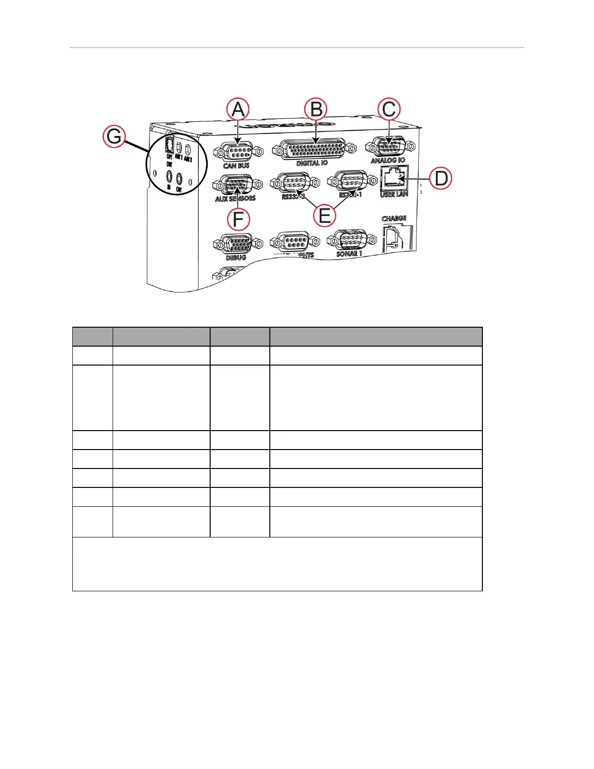
LD-250 Core Front, Upper
Figure 6-1 Front Upper LD-250 Core
ID Connection Type Description
A CAN Bus B DB9F Consult your local Omron Support for use.
B Digital I/O
a
HDB44F 16 digital inputs, in 4 banks of 4. Each bank can
be wired as active high or active low depending
on the connection of the BANK# terminal.
V
IN
range for each input is 0 to 30 V. The input
is ON when V
IN
> 4 V, OFF when V
IN
< 1.3 V.
C Analog I/O General use.
D User LAN RJ45 General Ethernet, Auto-MDIX, shielded
E RS-232 x 2 DB9M Port 1 and Port 2, general use
F Aux Sensors HDB15M Low front and optional side lasers
G Right-Side Con-
nectors
Various Not described in this manual.
a
16 digital outputs, protected low-side drivers. Wire these outputs to positive voltage through
the load. Output is open when OFF and grounded when ON. Each open-drain output is capable
of sinking 500 mA. May be used with loads connected to VBAT, AUX_20V, _12V, or _5V. You
must stay within the allowed current capacity of the VBAT or AUX power supplies.
Digital I/O
The LD-250 Core's Digital I/O HDB44F connector provides the user with digital inputs and out-
puts for payload customization.