194 LD-250 Platform User's Guide 20472-000 Rev B
10.2 LD-250 Specifications
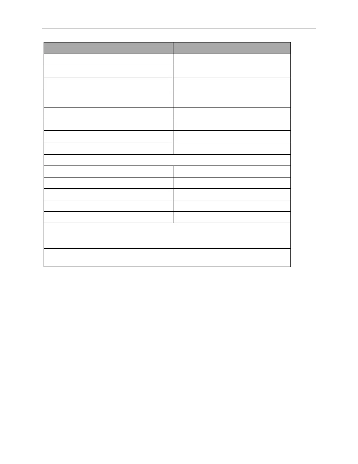
Description Specification
Triangle Target Drive Stop position repeatability +/-50 mm
Traversable step, max
a
10 mm
Traversable gap, max 15 mm
Climb grade. 3% (Frequent operation on grades affects
battery duration.)
Traversable terrain Generally, "wheelchair accessible"
Noise Level - Ambient 38 Db(A)
Noise Level - Peak 60 Db(A)
Minimum floor flatness
b
F
F
25 (based on the ACI 117 standard)
Battery
Run-time 8 hrs
Typical Lifespan 2000 charge cycles
Weight 19 Kg
Voltage 22-30 VDC
Capacity 72 Ah (Battery cell nominal)
a
Steps should have smooth, rounded profiles. A speed limit of600 mm/s is required for tra-
versing steps. Faster or frequent driving over such steps or gaps will shorten the lifespan of the
drive train components. Lower speeds may not traverse the step.
b
ACI 117 is the American Concrete Institute’s standard for concrete floors. F
F
is flatness, F
L
is
the level. Higher F
F
numbers represent flatter floors. F
F
25 is a fairly lenient specification.
Overhanging Payloads and the AMR Swing Radius
If your payload overhangs the default LD-250 footprint, it alters the AMR's swing radius and
exponentially affects its maximum safe rotational speed. Should the AMR size increase sig-
nificantly, you might need to adjust the AMR's maximum rotation speed to stay within 300
mm/sec or slower.
If you increase the AMR's default swing radius, reduce the value of the HeadingRotSpeed
parameter to compensate for its increased size and increased rotational speed.
For example, if you increase the AMR's radius to 625 mm and v represents threshold linear
velocity of 300 mm/s:
ω = v / r
ω = (300 mm/s) / (625 mm) = 0.48 radians/s
ω = 0.48 rad/s * 180/π = 27.5 deg/s
In MobilePlanner, set the value of the HeadingRotSpeed parameter to 27.5 deg/sec.