6-17
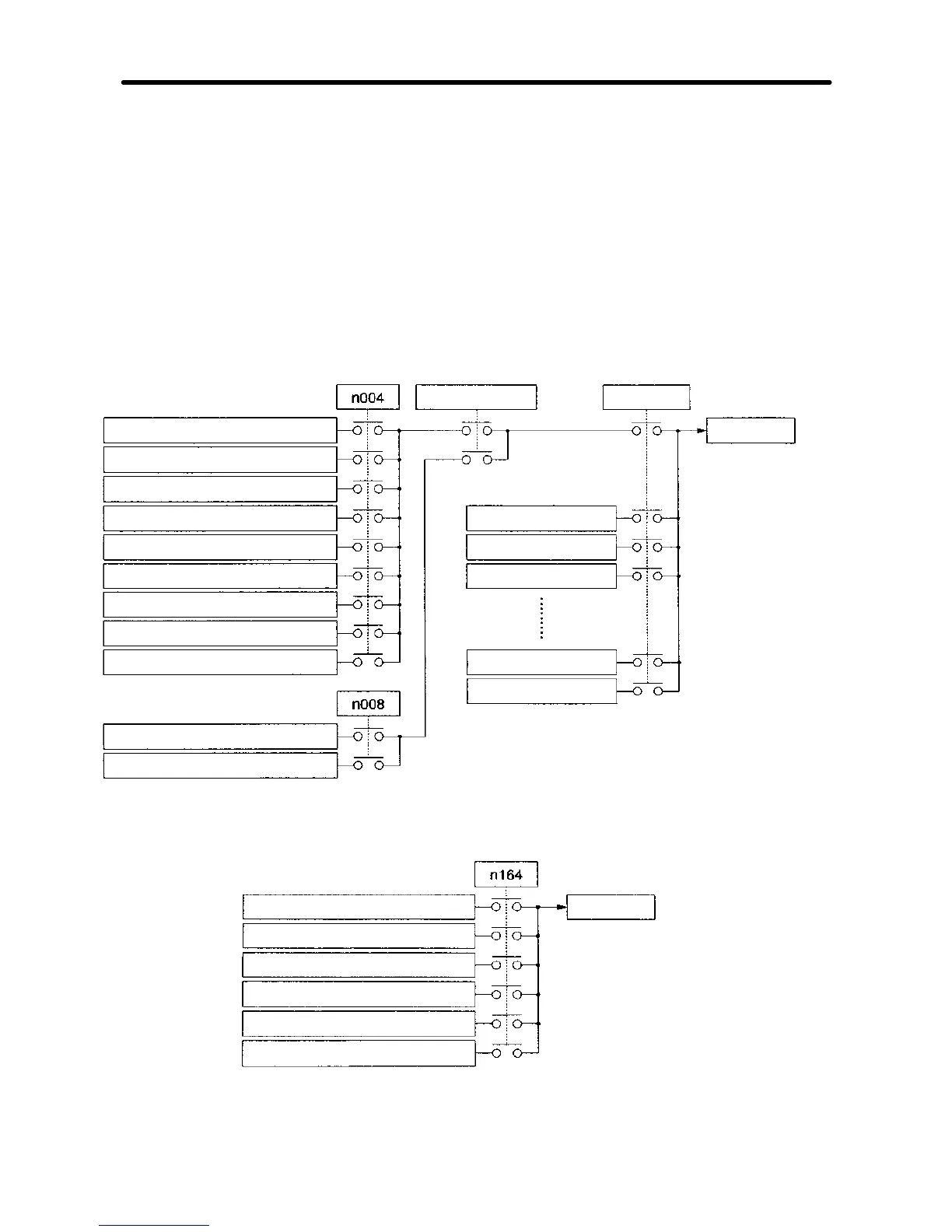
6-3-5 Input Selection of PID Control Target Value and
Detection Value
·Thetargetvalueanddetected value (feedback value) ofPIDcontrolaresetaccording
to n004 for frequency reference selection, n008 for local mode frequency reference
selection, and n164 PID feedback input block selection as shown in the following dia-
gram.
Make sure that the target value input and feedback value input do not overlap with
each other. Setting details are provided from the next page onward.
H Input Selection of PID Control Target Value
Local/Remote
Multi-step speed
reference
FREQUENCY adjuster of the
Digital Operator
Frequency reference 1 (n024)
External terminal (0 to 10 V)
External terminal (4 to 20 mA)
External terminal (0 to 20 mA)
Pulse train input
Communications frequency reference
Multi-function analog input (0 to 10 V)
Multi-function analog input (4 to 20 mA)
FREQUENCY adjuster of the
Digital Operator
Frequency reference 1 (n024)
Frequency reference 2 (n025)
Frequency reference 3 (n026)
Frequency reference 4 (n027)
Frequency reference 16 (n127)
Inching frequency (n032)
Target value
H Input Selection of PID Control Detection Value
Feedback value
External terminal (0 to 10 V)
External terminal (4 to 20 mA)
External terminal (0 to 20 mA)
Multi-function analog input (0 to 10 V)
Multi-function analog input (4 to 20 mA)
Pulse train input
Advanced Operation Chapter 6