7-10
7-2 Message Communications Basic Formats
The following description provides information on the format of message
data (DSR and response data).
Message communications of the Inverter conform to the MODBUS Com-
munications Protocol, which does not require message start and end pro-
cessing.
(The MODBUS Communications Protocol is a trademark of AEG
Schneider Automation.)
H Communications Format
·The following format is used for message data communications.
·Message data consists of a Slave address, function code, communications data, and
error check block.
Message data (DSR
message and response)
Slave address
1 byte
Function code
1 byte
Communications
data
Error check
block
2 bytes
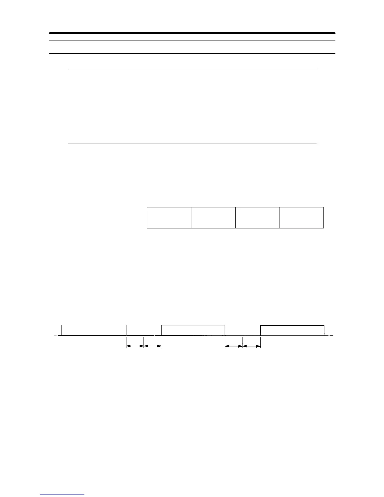
H Message Interval
·When the Inverter receives a DSR message from the Master, the Inverter waits for a
periodthatisequivalentto24bitsinlengthandaSendWaitTimesetinn156.Thenthe
Inverter will return a response.Set n156 according to the Master’s processing time or
the timing adjustment.
·When the Master issues the next message after receiving the response from the
Inverter, the Master mustwait fora24-bitperiod plus another periodof at least10ms.
DSR message from Master
Response from Inverter
DSR message from Master
24-bit (or 3-byte)
standby period
Standby period
set in n156
24-bit (3-byte)
standby period
Set a standby period of
10 ms or more for the
Master.
Communications Chapter 7