7-26
Note 2. No data can be written to multi-function input.
Note 3. The unit of setting of the broadcast message is different from that in the DSR
message to communicate with a single Slave.
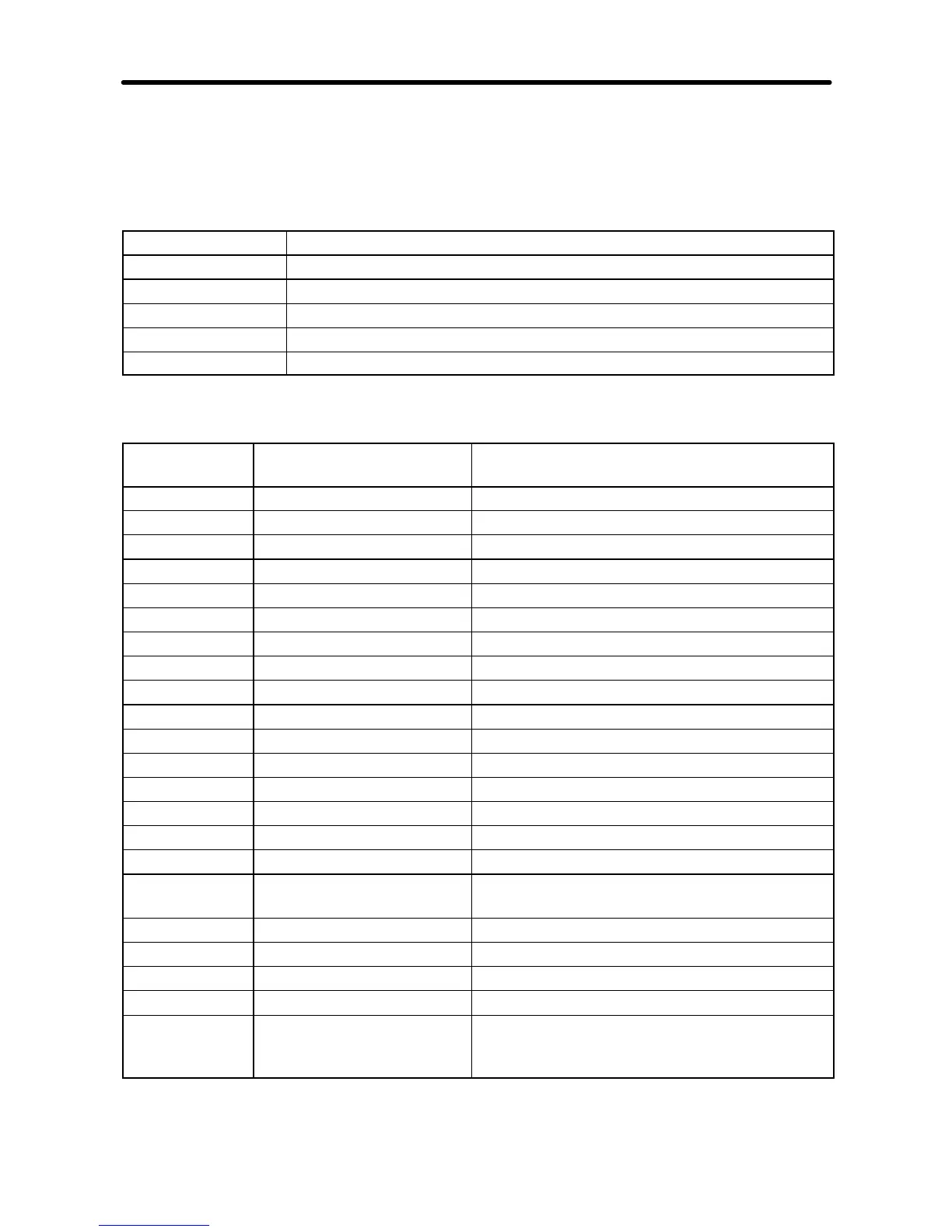
D RUN Command (Register 0001 Hex)
Bit No. Function
0 RUN command (1: RUN)
1 Forward/Reverse (1: Reverse)
2 External fault (1: External fault EF0)
3 Fault reset (1: Fault reset)
4 to 15 Not used
7-6-2 Monitor Functions
Register No.
(Hex)
Function Description
0020 Status signal Refer to the following corresponding table.
0021 Fault status 1 Refer to the following corresponding table.
0022 Data link status Refer to the following corresponding table.
0023 Frequency reference According to the set value in n152.
0024 Output frequency According to the set value in n152.
0025 to 0026 Not used ---
0027 Output current Read based on 1 A as 10.
0028 Output voltage Read based on 1 V as 1.
0029 Fault status (see note 2) Refer to the following corresponding table.
002A Warning (see note 2) Refer to the following corresponding table.
002B Input terminal status Refer to the following corresponding table.
002C Inverter status Refer to the following corresponding table.
002D Output terminal status Refer to the following corresponding table.
002E Refer to the following corresponding table.
002F to 0030 not used ---
0031 Main circuit DC voltage Read based on 1 V as 1.
0032 Torque reference Read based on ±1% as ±1 and the rated
motor torque is 100%.
0033 to 0034 Not used ---
0035 Read based on 1 [h] as 1
0036 Not used ---
0037 Output power Read based on ±1 kW as ±100.
0038 PID feedback Read based on 1% as 10 and a value
equivalent to the maximum frequency as
100%.
Communications Chapter 7