6-41
6-10 Other Functions
The following description provides information on the other functions and
parameter settings of the Inverter.
Refer to Section 7 Communications for parameters used for communica-
tions.
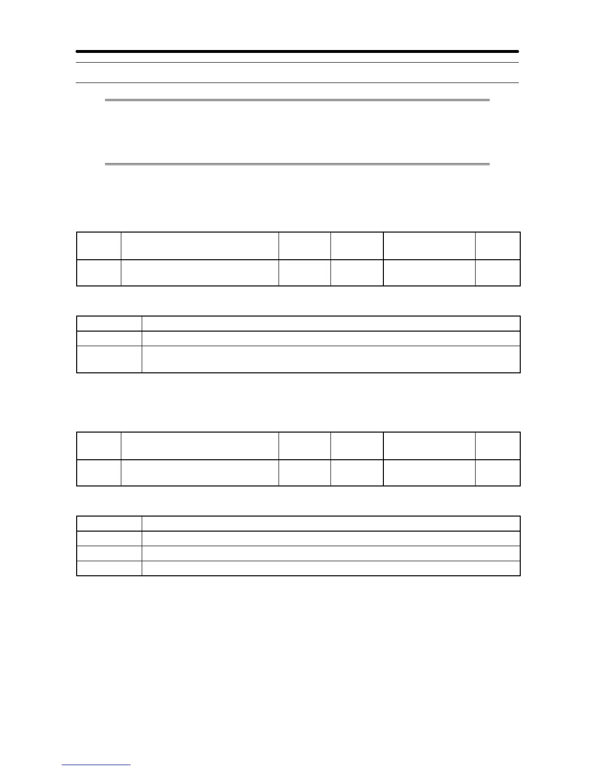
6-10-1 Digital Operator Disconnection Error Detection
·ThisparametersettingistoselectwhetherornottodetectDigital Operatorconnection
errors.
n010 Operation Selection at
Digital Operator Interruption
Register 010A
Hex
Changes during
operation
No
Setting
range
0, 1 Unit of
setting
1 Default setting 0
Set Values
Value Description
0 The Digital Operator connection error is not detected (Nonfatal error)
1 The Digital Operator connection error is detected (Error output and the
Inverter coasts to a stop)
6-10-2 Motor Protection Functions (n037 and n038)
·This parameter setting is for motor overload detection (OL1).
n037 Motor Protection
Characteristics
Register 0125
Hex
Changes during
operation
No
Setting
range
0 to 2 Unit of
setting
1 Default setting 0
Set Values
Value Description
0 Protection characteristics for general-purpose induction motors
1 Protection characteristics for Inverter-dedicated motors
2 No protection
·Thisparameterisusedtosettheelectricthermalcharacteristicsofthemotortobecon-
nected.
·Set the parameter according to the motor.
·If a single Inverter is connected to more than one motor, set the parameter to 2 for no
protection. The parameter is also disabled by setting n036 for rated motor current to
0.0. However, this is not recommended.
Advanced Operation Chapter 6