6-21
·Setn137tothefeedbacklevelinpercentagebasedonthefeedbacklevelatmaximum
frequency as 100%.
·Setn138in0.1-sincrementsforthepermissiblecontinuousperiodofthefeedbacksig-
nal level that is the same as or less than the feedback level set in n137.
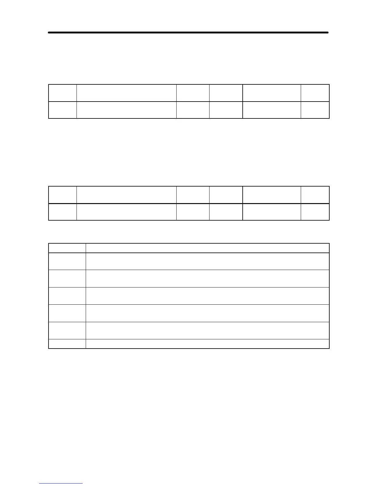
n163 PID Output Gain Register 01A3
Hex
Changes during
operation
No
Setting
range
0.0 to 25.0 Unit of
setting
0.1 Default setting 1.0
Set Values
·Set this parameter to a rate by which PID control value is multiplied for PID control.
·Normally, the default setting does not need to be changed.
·ThisparameterisusedfortheadjustmentofthePIDcontrolvaluetobeaddedwiththe
frequency reference.
n164 PID Feedback Input Block
Selection
Register 01A4
Hex
Changes during
operation
No
Setting
range
0 to 5 Unit of
setting
1 Default setting 0
Set Values
Value Description
0 Frequency reference control terminal for 0- to 10-V voltage input is enabled.
(see note 1)
1 Frequency reference control terminal for 4- to 20-mA current input is enabled.
(see note 2)
2 Frequency reference control terminal for 0- to 20-mA current input is enabled.
(see note 2)
3 Multi-function analog voltage (0- to 10-V) input is enabled.
Used only if two analog inputs are required in PID control.
4 Multi-function analog current (4- to 20-mA) input is enabled.
Used only if two analog inputs are required in PID control.
5 Pulse train reference control terminal is enabled. (see note 3)
Note 1. The maximum frequency (FMAX) is reached with 10-V input.
Note 2. The maximum frequency (FMAX) is reached with 20-mA input, if the SW2 on
the control PCB was changed from V (voltage) to I (current).
Note 3. Setn149forthepulsetraininputscaletothepulsetrainfrequencythatisequiv-
alent to the maximum frequency (FMAX).
Note 4. Make sure that the target value input and feedback value input do not overlap
with each other.
Advanced Operation Chapter 6