7-50
[10] + [00] + [01] + [00] + [02]
Set the constants contained in the DSR message.
Use Set Constant and set the constants in Hex.
<I>
The length is set in the length box. Insert the length by using the Insert icon. The
length is the number of bytes of the succeeding data (R(3N + 3), 4). The length is
automatically set by the CX-Protocol.
(R(3N+3), 4)
The Inverter’s actual data to be sent. This example selects Variable and Read R()
andsetstheoperand.SetDatato3N+3becausetheRUNcommanddatausesfour
bytes each from S + 3, S + 6, and S + 9.
Set Data Size to 0N + 4 so that it will be set to four bytes.
<c>
The check code is set in the check code box. Insert the check code by using the
Insert icon. All the data including the address data before the check code is oper-
ated.Markalltheitemsifthe ProtocolSupport Toolisused.Thecheckcode isauto-
matically set by the CX-Protocol.
·DSR Message to Read the Inverter Status
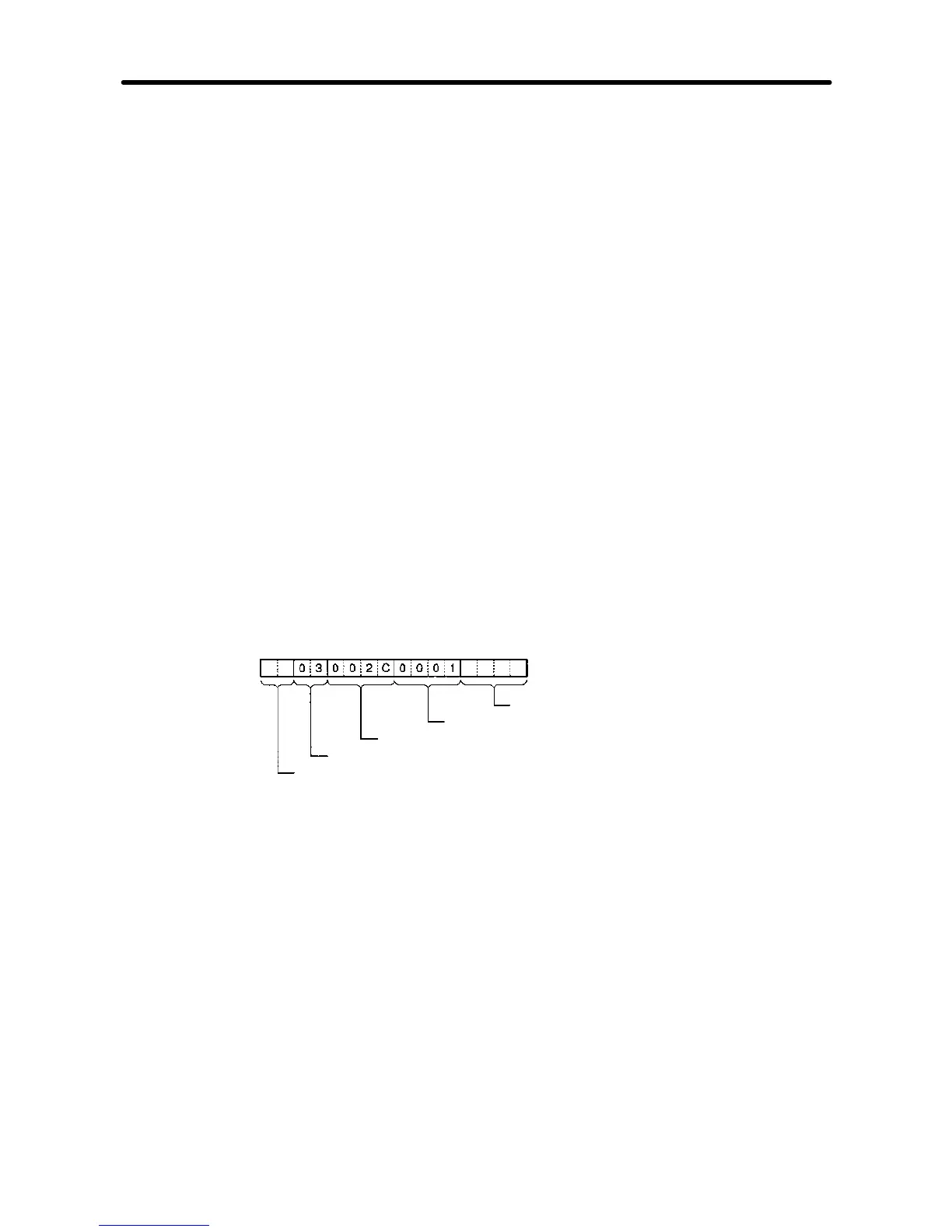
The DSR message to read the Inverter status from register 002C Hex consists of the
following items.
CRC-16 check (Set with <c>)
Number of read data registers: 1
Read start register number (Inverter status: 002C)
Function code (Read 03)
Slave address (Set with <a>)
Set data: <a> + [03] + [00] + [2C] + [00] + [01] + <c>
Set the address data, constant data, and check code data.
H Recv Message Detail Settings
1. With the left button of the mouse, click on List of Recv Messages. Then click on a
blank space with the right button of the mouse.
2. Select New and Recv Message.
The following table will appear. Set the send message in the table.
Communications Chapter 7