7-52
(N) of times to repeat the step.
SetDataSizeto1byteasadefault.Ifthedefaultvaluehasbeenchanged,setitto
0N + 1.
Data
Set the expected response in details.
·Response to the RUN Command and Frequency Reference
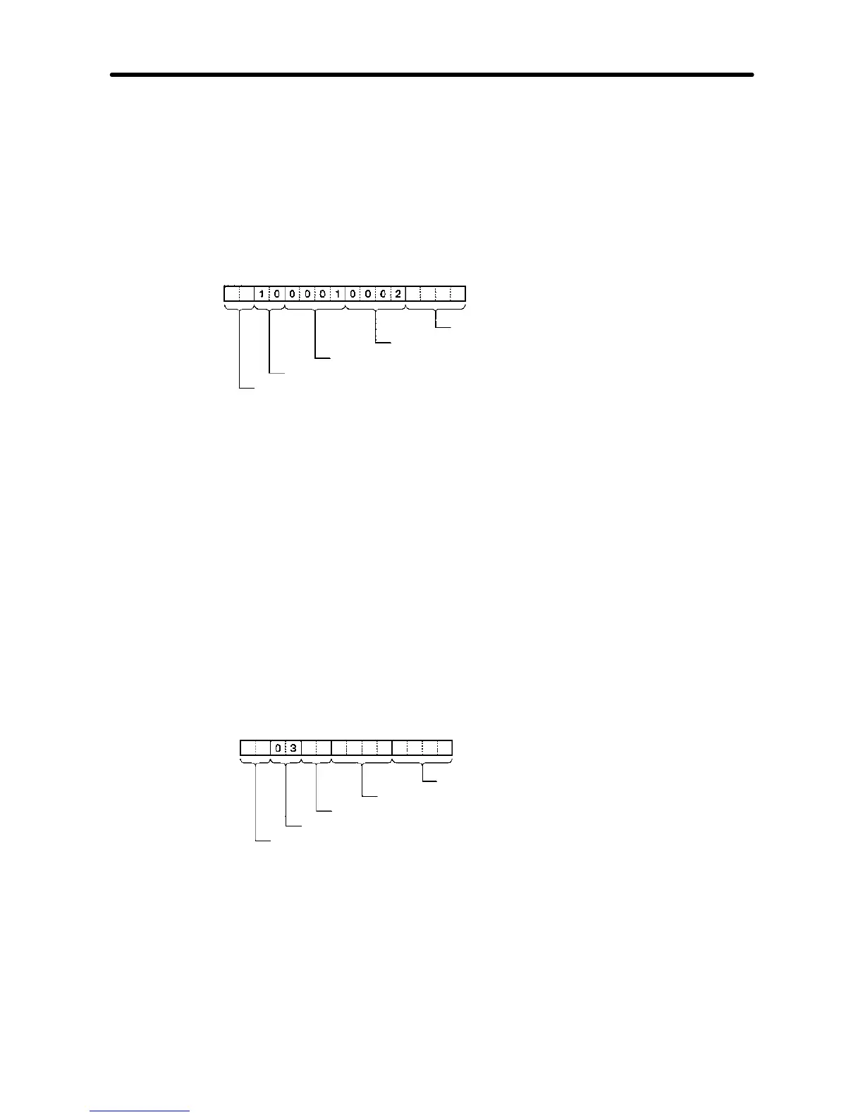
The response to the DSR message written consists of the following items.
CRC-16 check (Set with <c>)
Number of write data registers: 2
Write start register number (RUN command: 0001)
Function code (Write 10)
Slave address (Set with <a>)
Set data: <a> + [10] + [00] + [01] + [00] + [02] + <c>
<a>
The Slave address is setintheaddress box. Insert theaddress withthe Insert icon.
[10] + [00] + [01] + [00] + [02]
Set the constants contained in the response.
Use Set Constant and set the constants in Hex.
<c>
The check code is set in the check code box. Insert the check code by using the
Insert icon. All the data including the address data before the check code is used.
Mark all the items if the Protocol Support Tool is used. The check code is automati-
cally set by the CX-Protocol.
·Response to the Inverter Status Read
TheresponsetotheDSR message to request theInverterstatus inregister002CHex
consists of the following items.
CRC-16 check (Set with <c>)
Inverter status data (Set with variable)
Number of bytes of attached data (set with <l>)
Function code (Write 10)
Slave address (Set with <a>)
Set data: <a> + [03] + <I> + (W (1N + 1), 2) + <c>
<a., [03], <c>
The address data, constant data, and check code data are the same as the above.
<l>
Thelengthisset in the length box. Insertthelengthbyusingthe Insert icon. The length
Communications Chapter 7