2-25
H Wiring on the Input Side of the Main Circuit
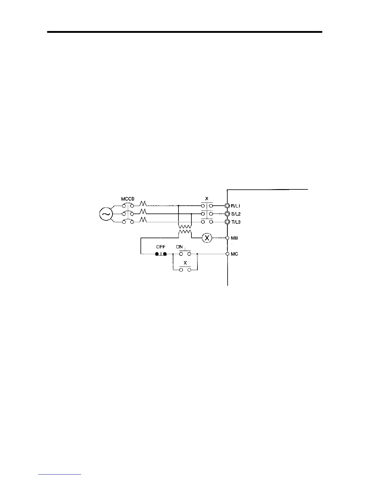
D Installing a Molded-case Circuit Breaker
Alwaysconnectthepowerinputterminals(R/L1,S/L2,andT/L3)andpowersupplyviaa
molded case circuit breaker (MCCB) suitable to the Inverter.
·Install one wiring circuit breaker per Inverter.
·Choose an MCCB with a capacity of 1.5 to 2 times the Inverter’s rated current.
·For the MCCB’s time characteristics, be sure to consider the Inverter’s overload
protection (one minute at 150% of the rated output current).
·IftheMCCBistobeusedincommonamongmultipleInverters,orotherdevices,setup
a sequence such that thepowersupplywill be turned OFFby a faultoutput, asshown
in the following diagram.
3-phase/
Single-phase
200 VAC
3-phase
400 VAC
Power
supply
Inverter
Fault output
(NC)
(see
note)
Note Use a 400/200 V transformer for a 400-V model.
D Installing a Ground Fault Interrupter
Inverteroutputsuse high-speedswitching,sohigh-frequency leakagecurrentisgener-
ated.
Ingeneral,aleakagecurrentofapproximately100mAwilloccurforeachInverter(when
the power cable is 1 m) and approximately 5 mA for each additional meter of power
cable.
Therefore, at the power supplyinput area, use a special-purposebreaker for Inverters,
which detects only the leakage current in the frequency range that is hazardous to
humans and excludes high-frequency leakage current.
Design Chapter 2