19
Nomenclature and Basic Operation Section 1-3
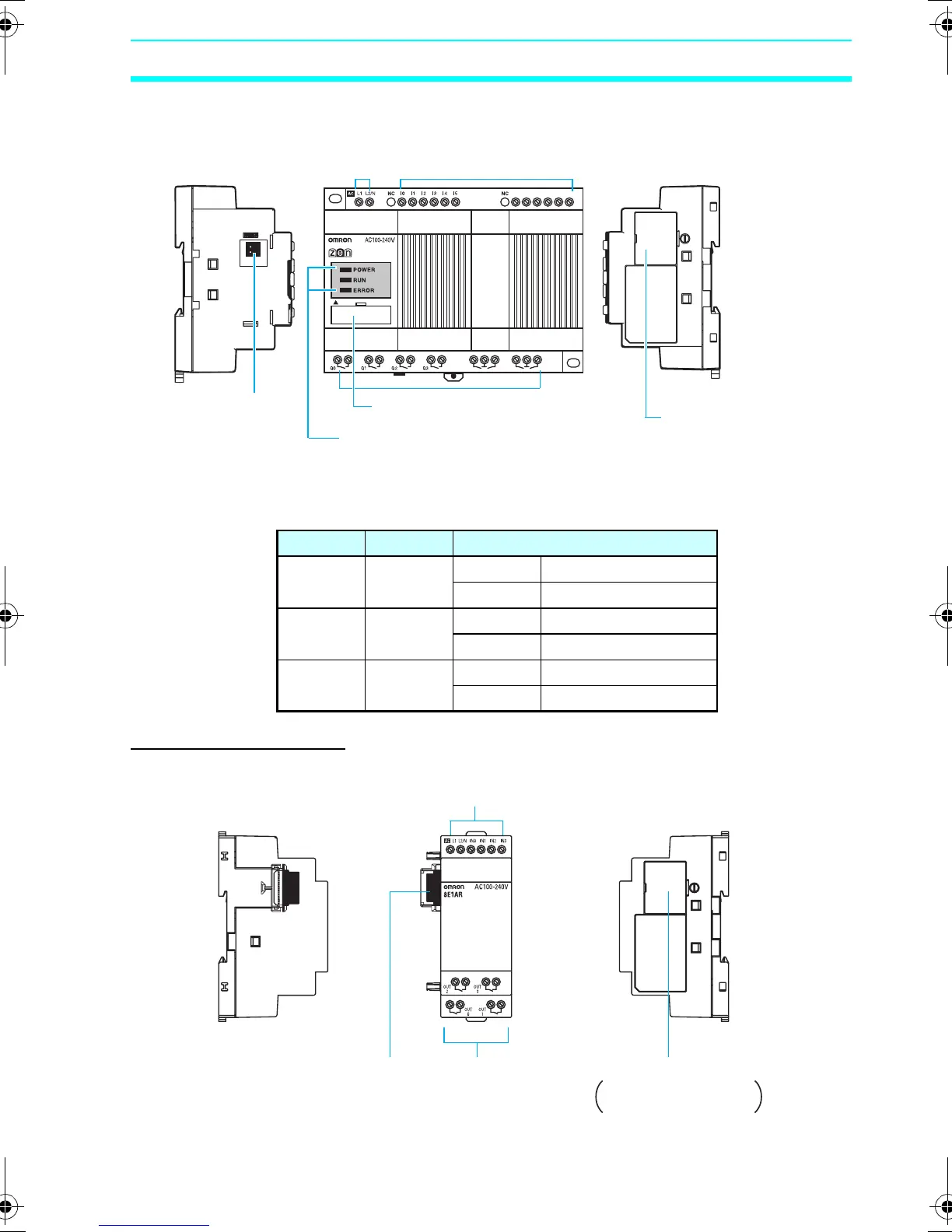
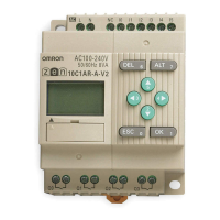
Models with 20 I/O Points
LED Indicators
Expansion I/O Units
Name Color Meaning
POWER Green Lit Power supplied
Not lit No power
RUN Green Lit Operating (RUN)
Not lit Stopped (STOP)
ERROR Red Lit Error
Not lit Normal
I
6
I
7
I
8
I
9
I
a
I
b
20C2AR-A-V2
Q
4
Q
6
Q
5
Q
7
Left Side Front
Power supply
terminals
Input terminals
Right Side
Battery Unit
connector
(Remove the
seal to connect
the Battery Unit.)
Output terminals
Personal computer
connector (also used for
Memory Cassette.)
LED indicators
Expansion Unit
connector cover
Remove this cover to
connect Expansion I/O Unit.
Left Side
Front
Input terminals
Right Side
Expansion Unit
connector
Output terminals
Expansion Unit connector cover.
Remove this cover to
connect Expansion I/O Unit.
Z211-E1-03.book Page 19 Friday, November 21, 2008 10:38 AM