36
Mounting Section 2-1
2-1 Mounting
2-1-1 Attention: Meeting the EC Low Voltage Directive
The ZEN is an open-structure device. The right side of the enclosure (i.e., the
vertical surface where the Expansion Unit connector cover is located) does
not provide the mechanical strength against impact of a 500-g, 50-mm-dia.
steel ball from a height of 1,300 mm, as required in IEC/EN 61131-2.
Therefore, the ZEN must always be mounted inside a control panel and the
installation method must assure protection from such impact by using one of
the following installation methods.
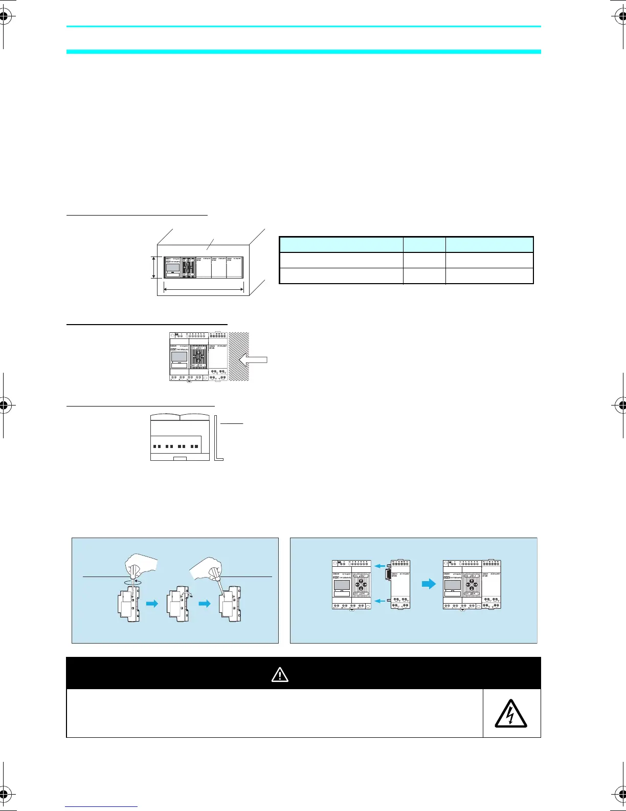
Protection by Cover
Protection by Location
Protection by Barrier
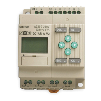
2-1-2 Connecting Expansion Units
Up to 3 Expansion Units can be connected.
A
B
▲
Cover plate
(e.g., control panel)
Cover Hole Dimensions
N = Number of Expansion I/O Units
CPU Unit A (mm) B (mm)
CPU Unit with 10 I/O points 47 70 + N
× 35 + 2
CPU Unit with 20 I/O points 47 122.5 + N
× 35 + 2
The area that needs to be protected against
mechanical impact. Install the ZEN close to the wall
of the control panel or in another location that will
protect it from mechanical impact.
▲
Bottom View
Barrier
Insert insulation between the barrier and the ZEN if the
barrier is made of metal or other conductive material.
If another device is used as the barrier, use a class I device.
Remove the cover screw with a Phillips screwdriver, insert a flat-blade
screwdriver into the gap around the cover, and remove the cover.
1 Remove the Expansion Unit connector cover from the side
of the CPU Unit.
2 Insert the guides on the Expansion Unit into the CPU Unit.
3 Press the Expansion Unit and the CPU Unit together until
you can hear the connectors mate completely.
Phillips screwdriver
Flat-blade screwdriver
CAUTION
Electrical shock may occur. Do not remove the Expansion Unit connector
cover unless an Expansion Unit will be permanently installed.
Z211-E1-03.book Page 36 Friday, November 21, 2008 10:38 AM