76
Using Timers (T) and Holding Timers (#) Section 3-6
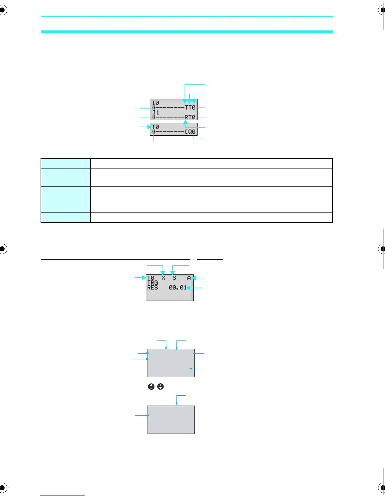
3-6-1 Settings in the Ladder Program Edit Screen
Timer triggers, reset outputs, and timer inputs are drawn on the Ladder
Program Edit Screen. Settings are made on the Parameter Settings
Screen.
3-6-2 Settings in the Parameter Settings Screen
All Timers Except Twin Timers (X, ■, O, F)
Twin Timers (W)
Timer address Timers: T0 to Tf (16 timers)/ Holding Timers: #0 to #7 (8 timers)
Trigger input T (TRG) Controls the timer trigger output. Triggers the timer when the trigger
input turns ON.
Reset input R (RES) Controls the timer reset output. When the reset input turns ON, the
present value is reset to 0 and the timer bit turns OFF. Trigger inputs
are not accepted while the reset input is ON.
Timer bit Turns ON according to the timer type.
Timer number
Trigger specification
Timer trigger output
Timer reset output
Reset specification
Time up output
Trigger input
Reset input
Timer address
Timer bit
Timer type Time unit
Monitor enabled/disabled
Set value
Timer address
▲ ▼
▲ ▼
TO W M:S A
ON-TIMER
TRG
RES 02.10
TO W H:M A
OFF-TIMER
TRG
RES 01.30
Timer type Time unit for ON time
Monitor enabled/disabled
Set value
Timer address
ON time
Time unit for OFF time
OFF time
to switch the display.
Z211-E1-03.book Page 76 Friday, November 21, 2008 10:38 AM