38
Wiring Section 2-2
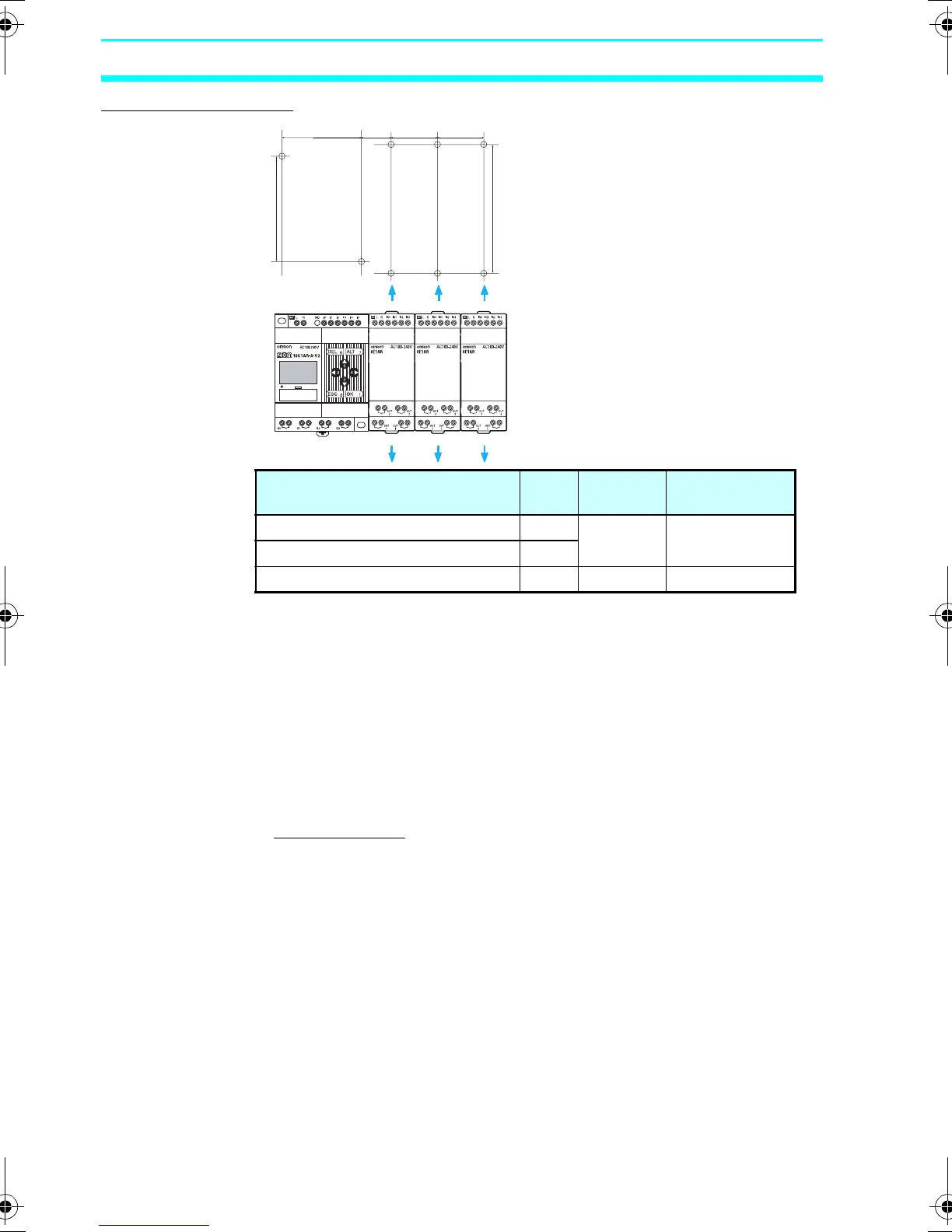
Surface Mounting
With an Expansion Unit, pull out the DIN Track mounting hooks on
the top and bottom of the Unit to secure the Unit with screws.
2-2 Wiring
2-2-1 External Wiring
Do not run ZEN I/O lines in the same duct or conduit as power lines.
■ Hanging Ducts
Leave at least 300 mm between the power cables and the I/O or
control wiring, as shown in the following diagram.
Unit A Screw
size
Tightening
torque
CPU Units with 10 I/O Points 60 M4 1.03 N·m max.
CPU Units with 20 I/O Points 112.5
Expansion I/O Units --- M3 0.46 N·m max.
80
A 22.5 35 35
97
Z211-E1-03.book Page 38 Friday, November 21, 2008 10:38 AM