44
Wiring Section 2-2
25 V or less (i.e., the OFF voltage for the ZEN) is 5 mA, as shown
in the residual voltage characteristic graph.
From the formulas given above,
R1 ≤ 25 V AC/1.7 mA= 14.7 kΩ
R2 ≤ 85 V AC/5 mA = 17 kΩ
The bleeder resistor must thus be 14 kΩ.
The Sensor output current in this case would be 100 VAC/14 kΩ,
or 7 mA. This satisfies the Sensor's control output range of 5 to
300 mA.
The bleeder resistor capacity is calculated as shown below and
must be 3 W.
P ≥ (110 V AC
2
)/14 kΩ × 3 = 2.59 W
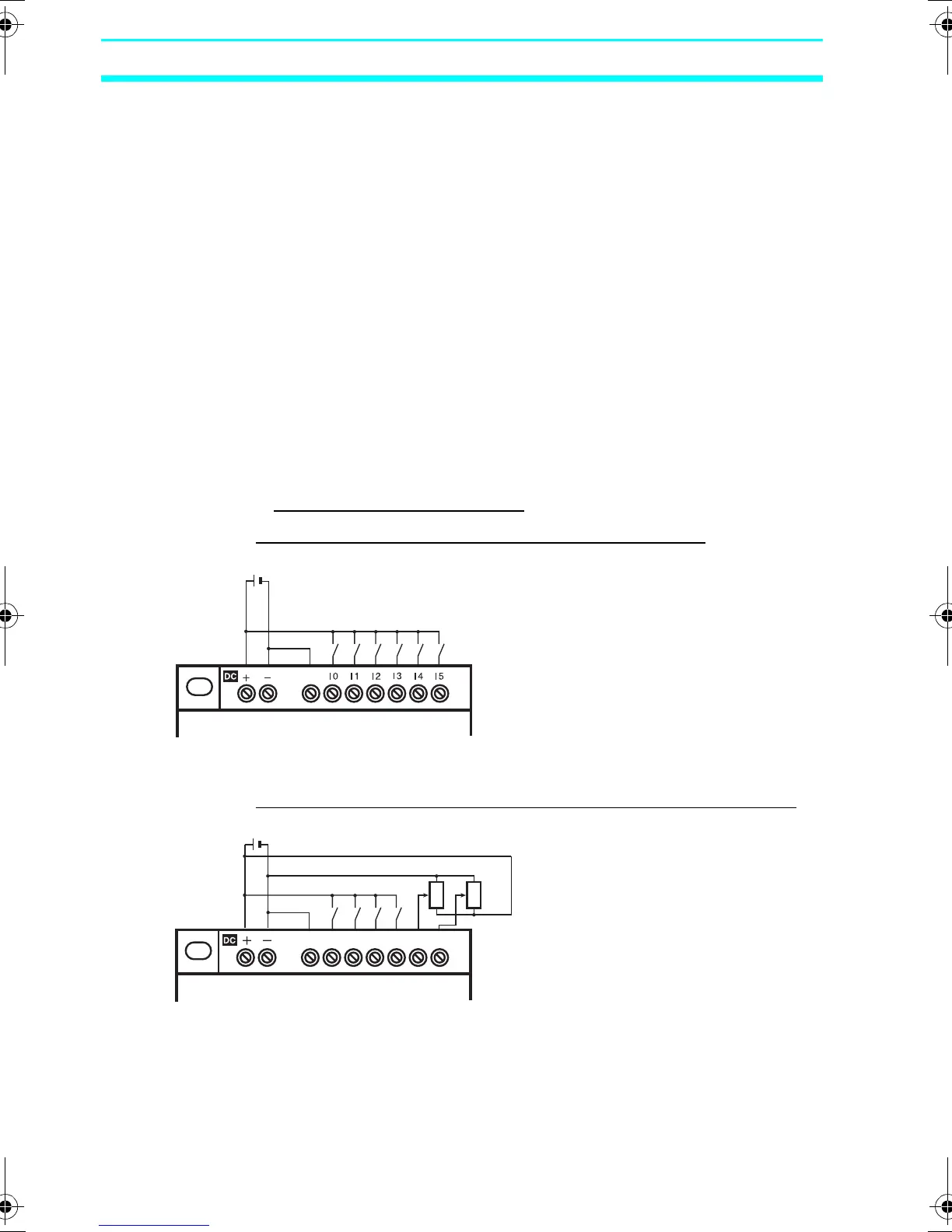
2-2-5 Wiring CPU Units with DC Power Supplies
Power Supply and Input Circuits
■ CPU Units with 10 I/O Points
Connecting a Negative Common (PNP Connection)
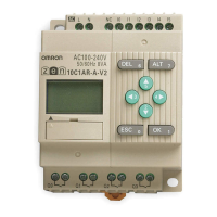
Connecting Analog Input Devices to Input Terminals I4 and I5
COM
CPU Unit with
10 I/O points
Input device
12 to 24 VDC
COM
I0 I1 I2 I3 I4 I5
CPU Unit with
10 I/O points
12 to 24 VDC
Note: When connecting an analog
input device, always connect
the negative side to the COM
terminal.
Z211-E1-03.book Page 44 Friday, November 21, 2008 10:38 AM