29
Memory Areas Section 1-4
1-4 Memory Areas
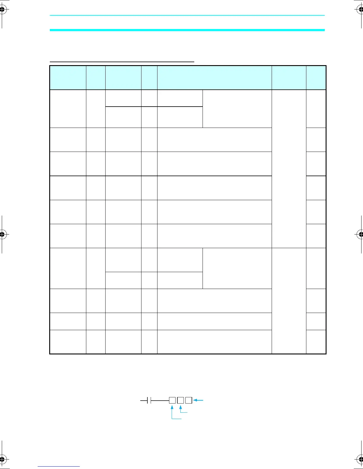
I/O, Work, and Internal Holding Bits
Note 1. Output bit Q3 of CPU Units with communications cannot be
output externally. It can be used as a work bit.
2. The following additional functions can be selected for bit outputs.
Name Type Bit
addresses
No.
of
bits
Function Ladder
programs
Page
CPU Unit
input bits
I 0 to 5 6 CPU Units
with 10 I/O pts
Reflect the ON/OFF
status of the input
devices connected to
the CPU Unit input
terminals.
N.O./N.C.
inputs
32
0 to b 12 CPU Units
with 20 I/O pts
Expansion
I/O Unit
input bits
X 0 to b 12 Reflect the ON/OFF status of the input
devices connected to the Expansion
I/O Unit input terminals.
32
Button
input bits
B 0 to 7 8 Turn ON when the operation buttons
are pressed in RUN mode. Cannot be
used for LED-type CPU Units.
99
Analog
comparator
bits
A 0 to 3 4 Output the comparison result for
analog inputs. Can only be used for
models with a 24-VDC power supply.
87
Compara-
tor bits
P 0 to f 16 Compare the present value of timers
(T), holding timers (#), and counters
(C), and outputs the comparison result.
91
8-Digit
comparator
bits
G 0 to 3 4 Compare the present value of 8-digit
counters (F) with a constant and
outputs the comparison result
94
CPU Unit
output bits
Q 0 to 3 4 CPU Units
with 10 I/O pts
(See note 1.)
Output the ON/OFF
status of the output
bits to the outputs
devices connected to
the CPU Unit.
N.O./N.C.
inputs
Outputs
(See note
2.)
32
0 to 7 8 CPU Units
with 20 I/O pts
Expansion
I/O Unit
output bits
Y 0 to b 12 Output the ON/OFF status of the output
bits to the outputs devices connected to
the Expansion I/O Unit.
32
Work bits M 0 to f 16 Can only be used within the program.
Cannot output to an external device.
-
Holding
bits
H 0 to f 16 Same as for work bits however the
holding bits maintain ON/OFF status
when power is turned OFF.
-
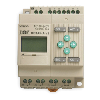
Execution condition
Bit address
Bit type
Additional function ([, S, R, A)
Z211-E1-03.book Page 29 Friday, November 21, 2008 10:38 AM