Chapter 2 - Introduction
2.6.1 System parts
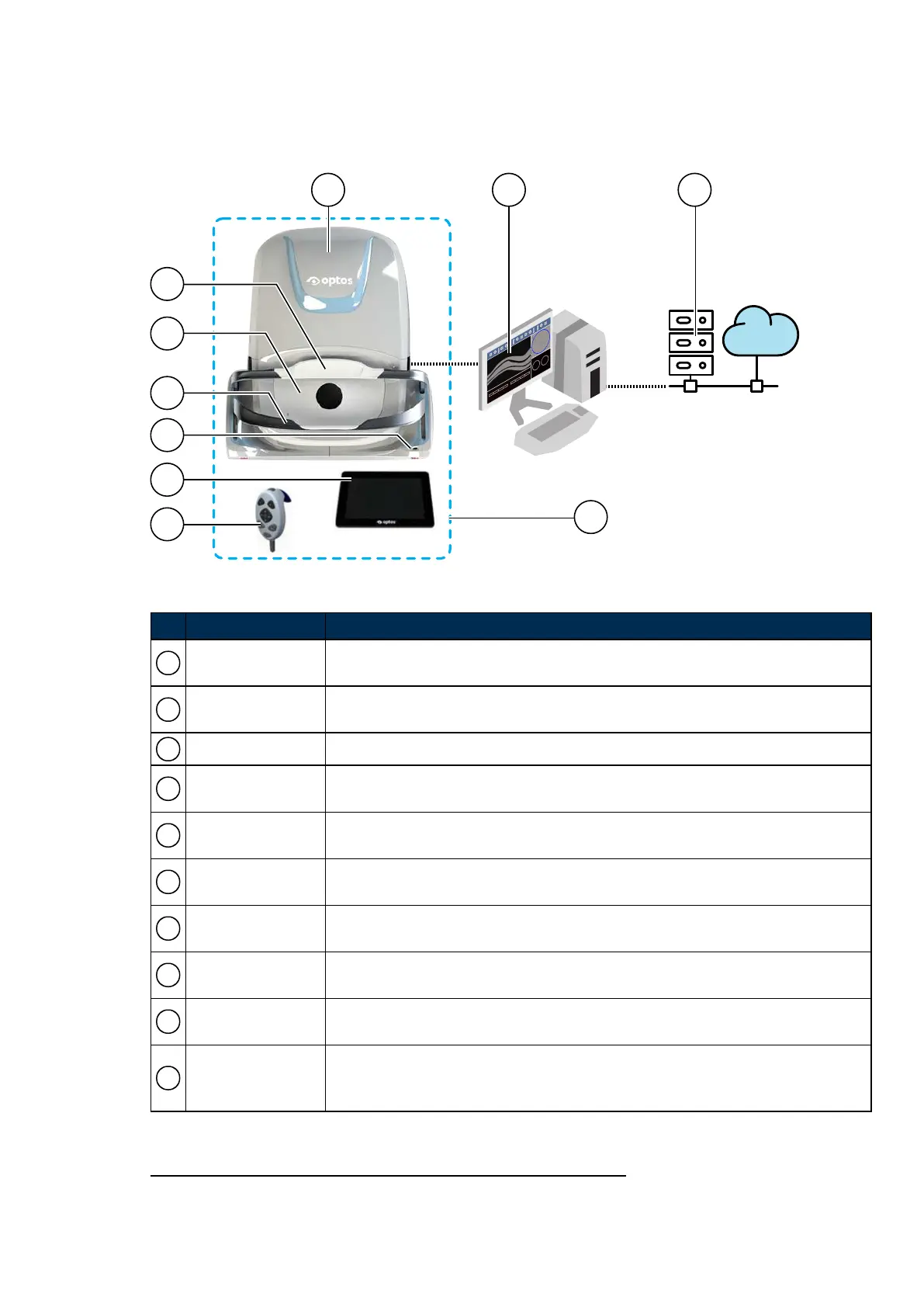
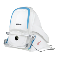
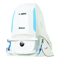
FIGURE 1: P200TE device connected to network
No. Name of Part Description
1 Scan head
The scan head comprises the light sources (lasers and SLD
1
) and electronics
used to capture patient images.
2 Head rest
The head rest supports the patient's head when the patient is being imaged, see
Using the chin rest and head rest on page34.
3 Face pad The face pad helps support the patient when the patient is being imaged.
4 Chin rest
The chin rest supports the patient's head when the patient is being imaged, see
Using the chin rest and head rest on page34.
5 Status indicator
The color changes to show the status of the device, see Status indicator on
page55.
6 Touch screen
The touch screen monitor is used to interact with the system. It displays
alignment feedback and captured images.
7 Hand control
The hand control comprises buttons used to adjust the patient alignment and
capture images.
8 Image server
Runs the OptosAdvance software and lets you manage the networked images.
The image server will also let you review and analyze patient images.
9 Customer network
Switches, Firewalls, Internet access, Review clients, Virtual image server (if
required)
10
Patient
environment
The image server, switch and any browser-based review clients or monitors must
be positioned outside the patient environment; more than 1.5 meters (5 ft) from
the scan head.
1.
Super Luminescent Diode
Part Number: G108707/8GME Page 23 of 75
Copyright 2018, Optos plc. All rights reserved. English