IV–31
● The designation (/) is used in the table to indicate indoor boards for DC and AC motor models.
● There is no TEST pin on the indoor board for AC motor models.
● See “5. Reference Document” for checking remote controller.
● For board and Electrical Wiring Diagram, see Chapter 6.
• Outdoor main board: page VI-2
• Outdoor power board: page VI-3
• Converter board: VI-4
• Indoor control board for DC motor models: page VI-5
• Outdoor Unit Electrical Wiring Diagram: page VI-6
● See instructions packaged with servicing indoor board for procedure on replacing indoor non-volatile
memory (EEPROM) and replacing indoor control board.
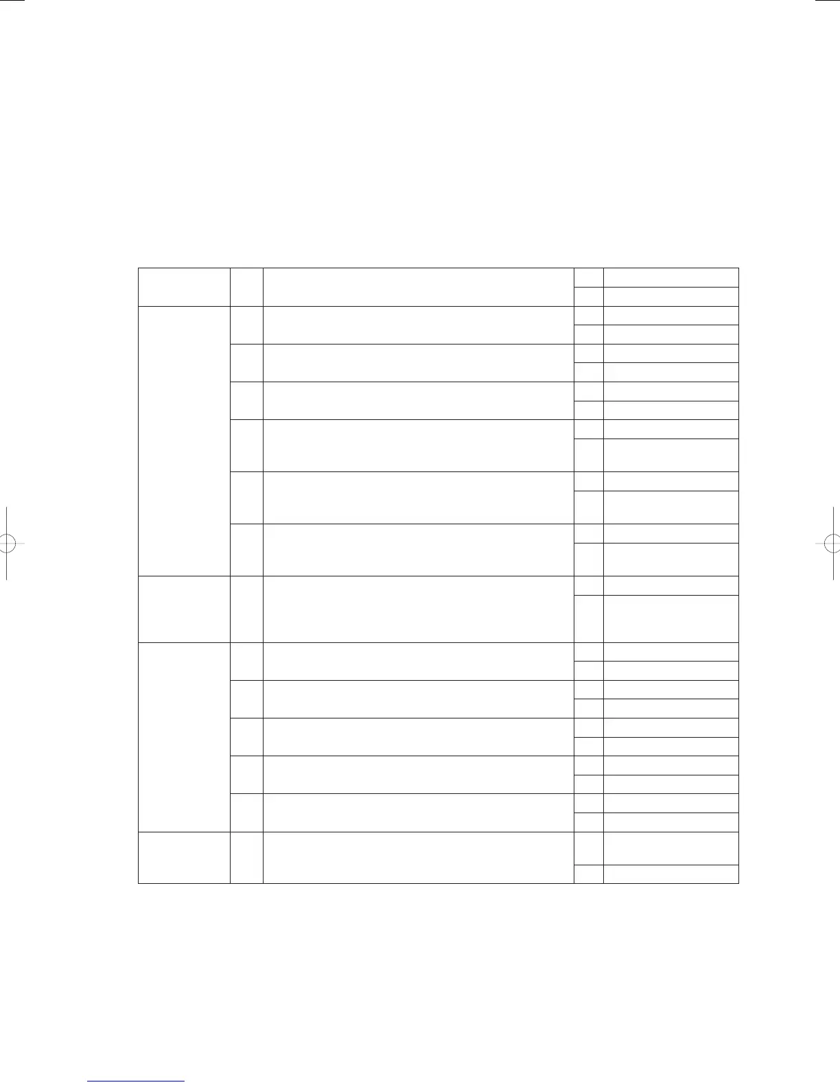
2) When the water heat exchanger unit is connected
1
Unit power
1-1
Is electricity being supplied to the water heat exchange
unit?
Yes 2-1
No Switch on the power
2
Remote
controller
(parallel array)
address
2-1 Has an address been set in the remote controller?
Yes 2-2
No Set the address
2-2
Is the address set in the remote controller a serial
number?
Yes 2-3
No Set a serial number
2-3
Do the addresses on the remote controller and on the
water heat exchange unit match up?
Yes 2- 4
No Match up t he addresses
2-4
Does the number of addresses on the remote controller
match up with the number of water heat exchanger units?
Yes 2-5
No
Match up the number of
connected units
2-5
Is the parallel array address on the water heat exchanger
unit set at anything other than [0]?
Yes 2- 6
No
Set any parallel array
address other than [0]
2-6
Is the parallel array address on the water heat exchanger
unit set at [1 - 5]?
Yes 3 -1
No
Set the parallel array
address at [1 - 5]
3
Terminating
resistance
3-1
Are the terminating resistance switches on the remote
controller and on water heat exchanger unit’s control
board located at both ends of the wire linking the remote
controller with the water heat exchanger unit set at [ON]?
Yes 4-1
No
Set the terminating
resistance for both ends
of the link wire to [ON]
4
Remote
controller
wires (wires
linking between
the remote
controller to
the water heat
exchanger unit)
4-1
Is the remote controller’s wire severed (connector or
terminal disconnected?)
Yes Repair the severed wire
No 4-2
4-2 Is the remote controller’s wire short-circuited?
Yes Repair the short-circuit
No 4-3
4-3 Is the remote controller’s wire grounded?
Yes Repair the ground
No 4-4
4-4 Is the remote controller’s wire polarity (+-) reversed?
Yes Switch the wires around
No 4-5
4-5
Are the remote controller wire (TB5-4, TB5-5) and outdoor
unit wires (TB1-(1), (2)) connected to the wrong places?
Yes Repair the wiring
No 5-1
5
Noise
5-1 Is a source of noise located nearby?
Yes
Set up noise
countermeasures
No 6-1
GHPtroubleshooting.indbIV‒31GHPtroubleshooting.indbIV‒31 2012/11/2611:20:082012/11/2611:20:08