IV–32
6
Water heat
exchanger
unit’s control
board and
surrounding
area
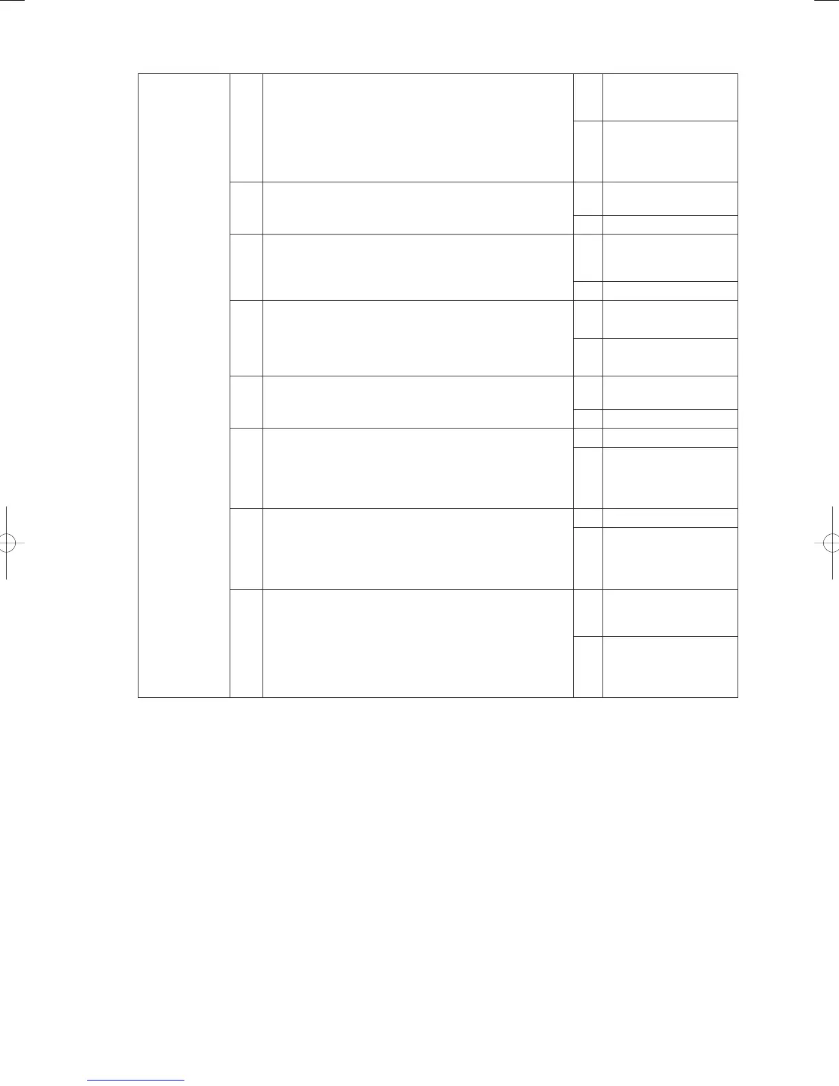
6-1 Is AC200V ±10% being applied between TB1 R and S?
Yes
Request improvements
to the power facility
manager
No
Proceed to 6-2 after
checking the wires and
terminals are normal
around TB1
6-2 Is the varister (VA1) grounded or severely deteriorated?
Yes
Replace the varister
(VA1)
No 6-3
6-3 Has the power switch (SW1) been switched on?
Yes
Proceed to 6-4 after
checking the wires
around SW1
No Set SW1 to ON
6-4
Are suitable DC voltages being applied to the circuits on
the board?
(Suitable DC voltage = approximately 5V between
TP1 and 2, approximately 7V between TP3 and 4, and
approximately 5V between TP5 and 6)
Yes 6 - 8
No 6-5
6-5
Is the varister (VA2) short-circuited between the phases or
severely deteriorated?
Yes
Replace the varister
(VA2)
No 6-6
6-6
Is electrical voltage being output to the secondary side of
the fuses (F1, F2)?
Yes 6 -7
No
Check that the wiring
and terminals around
the fuses are normal
and replace the fuses
6-7
Is electrical voltage being output to the secondary side of
the noise fi lter (RF1?)
Yes 6 - 8
No
Check that the wiring
and terminals around
RF1 are normal and
replace the RF1
6-8
Is electrical voltage being output to the secondary side of
the power transformer (PT1?)
Yes
Replace the water heat
exchanger unit’s control
board
No
Check that the wiring
and connectors around
PT1 are normal and
replace the PT1
● See “5. Reference Document” for details on the procedure for replacing the water heat exchanger unit’s
control board.
● For board and Electrical Wiring Diagram, see Chapter 6.
• Outdoor main board: page VI-2
• Outdoor power board: page VI-3
• Converter board: VI-4
• Indoor control board for DC motor models: page VI-5
• Outdoor Unit Electrical Wiring Diagram: page VI-6
GHPtroubleshooting.indbIV‒32GHPtroubleshooting.indbIV‒32 2012/11/2611:20:082012/11/2611:20:08