Installation
2
10
chaPter 2
Installation
Note: Some of the following manual sections con-
tain information in the form of warnings, cautions
and notes that require special attention. Read and
follow these instructions carefully to avoid personal
injury and damage to the instrument. Only person-
nel qualified to do so, should conduct the installa-
tion tasks described in this portion of the manual.
Environmental Conditions
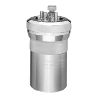
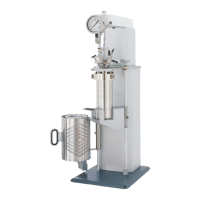
The 6400 Calorimeter is completely assembled
and given a thorough test before it is shipped from
the factory. If the user follows these instructions,
installation of the calorimeter should be completed
with little or no difficulty. If the factory settings
are not disturbed, only minor adjustments will
be needed to adapt the calorimeter to operating
conditions in the user’s laboratory.
This apparatus is to be used indoors. It requires at
least 0.4 m
2
(4 sq ft) of workspace on a sturdy bench
or table in a well-ventilated area with convenient
access to an electric outlet, running water and a drain.
Required Consumables, Utilities & Power
Requirements
The 6400 Calorimeter requires availability of
oxygen, 99.5 % purity, with appropriate connec-
tion, 17 MPa (2500 psig), maximum.
The 6400 Calorimeter requires availability of
nitrogen or air, oil and water free, with appropriate
connection, 17 MPa (2500 psig), maximum.
Approximately 16 L of distilled water are required
to fill the external pressurized rinse tank.
Approximately 2 L of distilled, de-ionized, or tap
water, with a total hardness of 85 mg/kg (85 ppm)
or less, are required for filling the internal cooling
reservoir.
The power requirements for the sub-assemblies of
the 6400 Calorimeter are:
Calorimeter
120 VAC, 5.0 Amps. 50/60 Hz
240 VAC, 3.0 Amps. 50/60 Hz
1759 Printer
100 to 240 VAC, 1.4 Amps 50/60 Hz
1759 Printer Supplies
334C Printer Paper
381C Printer Ribbon
Electrical Connection
Plug the power line into any grounded outlet
providing proper voltage that matches the
specification on the nameplate of the calorimeter.
Grounding is very important not only as a safety
measure, but also to ensure satisfactory controller
performance. If there is any question about the
reliability of the ground connection through the
power cord, run a separate earth ground wire to
the controller chassis.
Turn the power switch to the ON position. After
a short time, the ynapmoC logo will appear on the LCD
display followed by a running description of the in-
strument boot sequence. When the boot sequence
is complete, the Main Menu is displayed.
Front Panel Meter
The panel meter on the front of the calorimeter
controls the temperature of the water in the in-
ternal cooling resorvoir. The setpoint is locked at
15°C. A red light will flash in the upper left corner
of the display when the water is being cooled.