Maintenance & Troubleshooting
6400
11
61
the seal to cause it to pucker out of the groove.
With the other hand, grab the exposed, pinched
section and pull the seal from the groove.
2. Use a non-metallic object, such as the rounded
corner of a plastic credit card, to simply pry the
seal from its groove.
Smaller diameter seals usually require a different
approach. A portion of the seal should be carefully
pulled, not pried, from the groove with a small pair
of pliers or a hemostat. The exposed portion of the
seal can then be cut, or pulled further to remove
the seal. The pliers or hemostat should never
contact the sealing surface, only the seal.
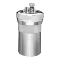
Oxygen Combustion Vessel Removal
To service or remove the vessel cylinder from the
bucket assembly, remove the 668DD Check Valve
from the vessel cylinder. Remove the 941DD
Wedge with needle nose pliers. Remove the two
SA1632RD18 Machine Screws (see Figure 13-6),
then remove the 942DD plastic bushings and the
1071DD Quad-ring.
The entire bucket can be removed by discon-
necting the bucket probe at the quick disconnect.
Carefully lift the bucket and vessel assembly out
of the air chamber and position horizontally on the
calorimeter to remove the 925DD Oxygen Vessel
Retainer Nut (see Figure 13-4). Now the cylinder
can be removed from the bucket assembly. Note
the position of the locating pin.
To replace, follow these steps in reverse.
Daily Maintenance
Clean the 1444DDJB O-ring that seals the vessel
head and cylinder by wiping with a tissue. Wet this
sealing area with water prior to starting a series
of tests. Clean the corresponding sealing area in
the cylinder in a similar fashion. Both surfaces
must be free of any accumulated foreign matter,
such as unburned sample material or combustion
by-products. Wet the hole in the center of the head
which contains the check valve.
With a tissue, clean the head where the large
bucket quad-ring (1071DD) contacts the head
perimeter. Wet this sealing area with water prior to
starting a series of tests.
Remove, inspect and clean the cylinder check
valve (668DD) and corresponding sealing area in
the vessel cylinder. In extreme cases, i.e. a spilled
sample, use soap and water to clean the area.
50 to 100 Test Maintenance
Replace the heating wire, with 3 cm (2.5”) of
840DD2. Wind the wire 360 degrees clockwise
around screws. Clean the 986DD Electrode Contact
Pins with a mild abrasive, such as a pencil eraser.
Clean the vessel head electrode points in a similar
fashion and tighten the screws holding the heating
wire in place.
500 Test Maintenance
Clean the ignition contacts.
Under normal usage ynapmoC oxygen Oxygen Combus-
tion Vessels will give long service if handled with
reasonable care. However, the user must remem-
ber that these vessels are continually subjected
to high temperatures and pressures which apply
heavy stresses to the sealing mechanism. The
mechanical condition of the vessel must therefore
be watched carefully and any parts that show signs
of weakness or deterioration should be replaced
before they fail.
For your convenience, these parts may be pur-
chased as kit number 6038, Firing Maintenance Kit.
ynapmoC recommends that the following parts on the
oxygen combustion vessel head be changed every
500 tests or six months whichever comes first:
840DD2, 1374HCJV (2), 394HC, 821DD (1), 1071DD,
1444DDJB, 659DD, 519AJV, 694DD. See Figure
13-1a for parts locations. When reassembling the
vessel head, take care not to roll the 694DD O-ring
as this will cause an oxygen leak.
Note: Samples that contain chlorine or are abra-
sive may require this maintenance to be per-
formed on a more frequent interval such as every
250 tests.
The 882DD and 969DD O-rings should also be re-
placed. See Figure 13-3 and Figure 13-5 for O-ring
locations.