Menu Descriptions
34
5
CONTROL CHART PARAMETERS: A control chart
is a graphical tool which can assist the user in
determining whether or not their process is in
control. Many standard methods will dictate that a
reference sample be measured periodically and the
results plotted on a graph. Limits for acceptable
values are defined and the process is assumed
to be in control as long as the results stay within
these limits. Since results are expected to scat-
ter with a normal distribution within established
limits, systematic trends or patterns in the data
plots may also be an early warning of problems.
CHARTED VALUE: Toggles the charted value
between the HOC Standard (Heat Of Combus-
tion of Standard) and Energy Equivalent.
PROCESS SIGMA: In relation to calorimetry,
sigma is used as the classification of the instru-
ment. The higher the process sigma the higher
the limits for acceptable values for precision
control.
Note: The 6400 is a 0.1 Process Sigma calorimeter.
TEMP. RISE HIGH WARNING: Sets a limit for
the temperature rise during a test. If the tem-
perature rise exceeds the limit the user will be
warned.
TEMP. RISE LOW WARNING: Sets a lower limit
warning for the temperature rise during a test.
If the temperature rise is lower than this setting
the user will be warned.
USE BOMB: Displays the ID of the bomb currently
being used in the Calorimeter and toggles through
the four possible bomb numbers.
BOMB 1 - BOMB 4: Leads to sub-menu, Bomb 1 -
Bomb 4. Displays standardization information for
bomb and bucket combinations. While only one
bomb and bucket is installed in the calorimeter at
a time, a spare may be used for servicing and for
more rapid turn-around. The respective EE values
for each bomb can be stored in memory.
Note: For rapid turn around between tests, the user
may wish to use an extra head. Each head should
be assigned a bomb ID. On the Data Entry Controls
Menu, set the Prompt for Bomb ID to “ON”.
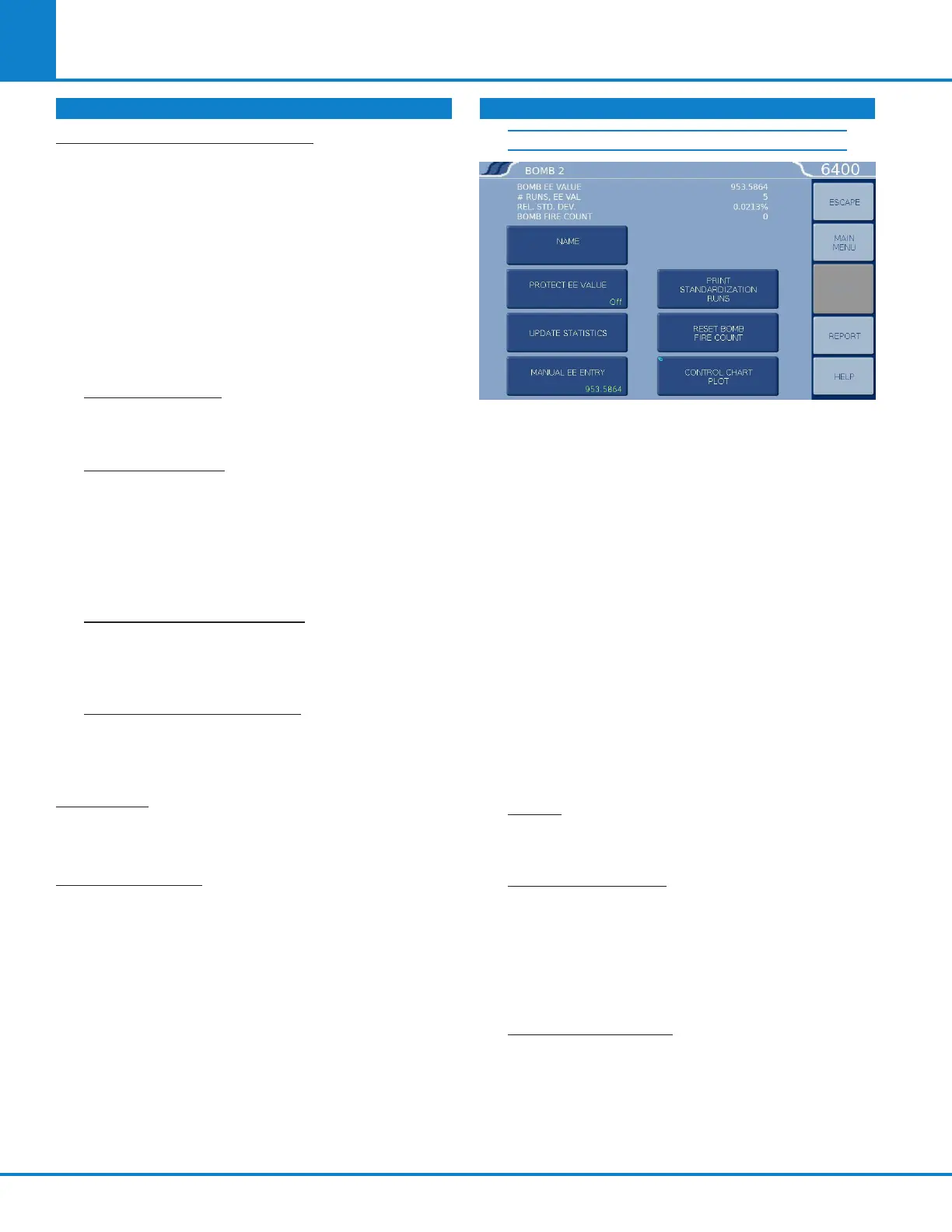
BOMB 1
The following four values are displayed for the
Bomb # shown in the title on top of the screen.
» BOMB EE VALUE. Displays the calculated
EE value.
» # RUNS, EE VAL. Displays how many runs
have been used to determine the EE value.
» REL. STD. DEV. Displays the relative stan-
dard deviation for the series of tests used to
determine the current EE value in percent
of the EE value.
» BOMB FIRE COUNT. Displays the current
bomb firing count or the number of times
the bomb has been fired since it was last ser-
viced. When this count matches the limit set
by Bomb Service Interval (on the Calibration
Data and Controls screen), the user will be
informed that the bomb is ready for service.
NAME: Enables the operator to assign a
unique alpha-numeric label for the bomb ID.
The ID can be up to 8 characters.
PROTECT EE VALUE: Toggles between OFF
and ON. When set to OFF, the 6400 automati-
cally updates the EE value as new tests are run.
When set to ON, it keeps the EE value protect-
ed, whether it has been revised manually via
the Manual EE Entry key or calculated by the
instrument.
UPDATE STATISTICS: If the Protect EE Value is
set to OFF, pressing this key will cause the EE
Value for this Calorimeter to be updated using
all standardization runs currently in memory to
the limit established in the Calibration Data and
Controls menu. If the Protect EE value is set to
ON, this key is not functional.
CALIBRATION DATA AND CONTROLS (CONTINUED) CALIBRATION DATA AND CONTROLS (CONTINUED)