Installation
6400
2
13
Water Connection
Remove the cap plug on the water filling elbow and
fill the internal reservoir tank with water having a
total hardness of 85 mg/kg (85 ppm) or less, until the
water level is at the bottom of the filling elbow. The
calorimeter water tank will initially accept about 2 L.
CAUTION! It is important to ensure
there is no spillage of water onto the unit
while filling the internal reservoir tank.
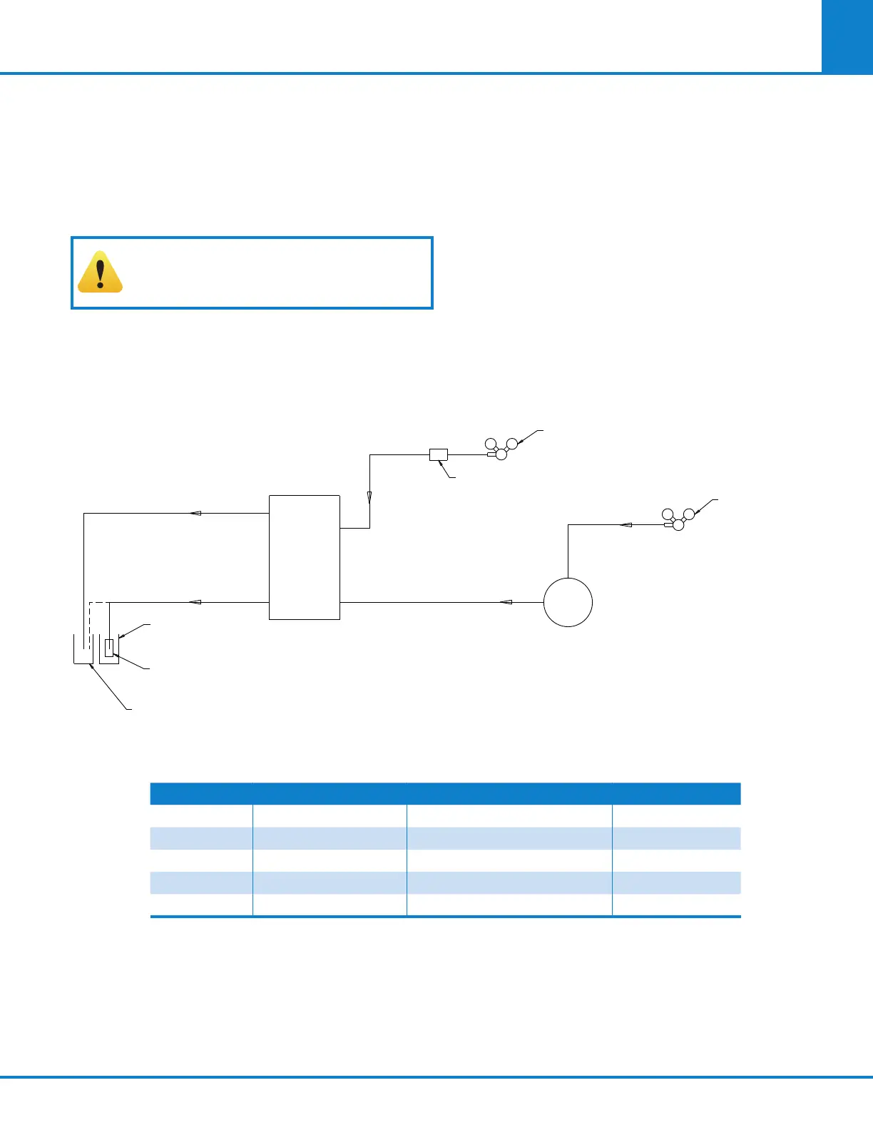
Figure 2-3: 6400 External Plumbing
Fill the external rinse tank with about 16 L of dis-
tilled water through the large opening at the top of
the tank. The cover for this opening is removed by
lifting up on the handle, pushing down on the lid,
tilting and removing. Replace and close the cover
after filling.
The connection between the calorimeter and the
A1589DD Rinse Tank should be made with a piece
of 1/8” nylon pressure hose (HX0012TB024). See
Figure 1-3 below.
Tube No. Part No. Description Max Length
1 HX0012TB024 1/8” OD, Nylon 1.5 m (5 ft)
2 HJ0025TB035 1/4” OD, Nylon 1.5 m (5 ft)
3 HX0012TB024 1/8” OD, Nylon 1.5 m (5 ft)
4 HX0012TB024 1/8” OD, Nylon 3 m (10 ft)
5 HX0038TB062 3/8” OD, Bev-A-Line 3 m (10 ft)
6400
CALORIMETER
VENT
4
5
1
3
EXHAUST
OR
PLASTIC CONTAINER
(231C2)
RINSE CONTAINER ASSEMBLY
(A1050DD)
BOTTLE SUPPORT
(1054DD)
OXYGEN
(359VB)
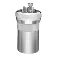
IN-LINE FILTER
ASSEMBLY (435 PSIG)
(A570DD)
RINSE WATER
RINSE
TANK
A1589DD
PNEUMATIC SUPPLY
NITROGEN REGULATOR
ASSEMBLY (80 PSIG)
(A812DD)