Maintenance & Troubleshooting
64
11
Troubleshooting
Vessel Exhaust Troubleshooting
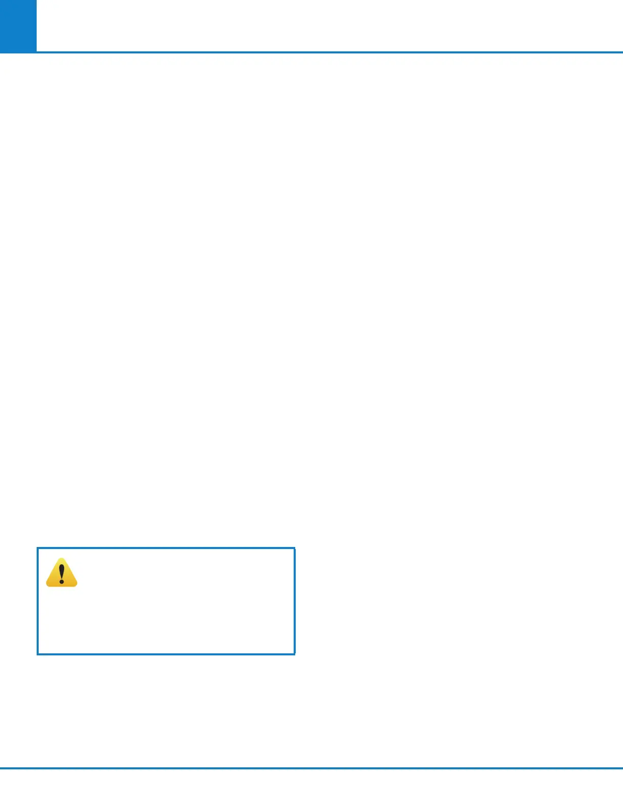
The vessel exhaust and sealing is controlled by
movement of the 966DD2 piston inside of the
1140DD vessel seal/release cylinder. This assembly
is mounted on the bottom of the calorimeter air can.
The piston is driven to the up position (exhaust)
by applying oxygen at 30 bar to the 1/8 male con-
nector (344VB). The piston is driven down (vessel
seal) by applying pressure to the 376VB elbow. The
application of the oxygen pressure is controlled by
the A1251DD three station solenoid valves. There
is a flow restrictor, part 527VB, on the inlet side of
this solenoid which limits the maximum flow rate
of oxygen and in turn creates a gradual increase in
pressure at the 1140DD vessel seal/release cylinder
when the solenoid is turned on. Failure of the
vessel to exhaust in a timely fashion can have more
than one cause. Certain causes can be eliminated
systematically by checking the vessel exhaust dif-
fuser, at the end of the vessel exhaust line, for any
restrictions in the six small cross drilled holes. This
fitting should be removed from the tubing, inspected
thoroughly and cleaned as required.
Service the O-rings on the 966DD2 Piston
This process is described in the 500 test mainte-
nance section.
Confirm function of the 966DD2 piston
In order to reduce the amount of time it takes to
duplicate and troubleshoot this type of situation,
the I/O diagnostics can be used to pressurize and
exhaust the vessel without having to run lengthy
combustion or pre-tests.
CAUTION! This screen allows uncon-
ditional and arbitrary output control
for testing purposes. Be aware that
all user and instrument protection is
disconnected while on this screen. This
is very important and you should take
proper precaution.
1. Make sure the 668DD check valve is installed at
the bottom of the cylinder.
2. Lock the head into the cylinder and close the
calorimeter lid.
3. Confirm the Exhaust is off.
4. Turn BOMB SEAL on then off to retract the
966DD2 piston.
5. Turn on O2 FILL to begin filling the combustion
vessel. The vessel will be completely filled in
one minute, at which time O2 FILL should be
turned off. This seats the check valve in the head
which in turn seals the contents of the vessel.
6. The calorimeter lid can be unlocked at this time.
7. Activating the Exhaust should initiate a vessel
exhaust within two seconds. If it takes much
longer than two seconds before the combus-
tion vessel begins to vent, then at least one of
the following conditions outlined below exist.
If the vessel exhaust is initiated in a timely manner
but fails to complete in 10 seconds, a blockage or
restriction in the vessel exhaust circuit is indicated.
This must be investigated and corrected.
If the vessel fails to exhaust, the 899DD Head
Handle and SN1632HX 8/32 Hex Nut can slowly be
removed to release the pressure in the combustion
vessel. See Figure 13-1.
If the piston moves properly with no applied
combustion vessel pressure, but still fails to initiate
an exhaust of a pressurized combustion vessel in a
timely fashion, at least one of the following condi-
tions exist:
1. The 527VB restrictor is partially blocked.
2. The exhaust line is blocked.
3. There is a gas leak between the outlet of the
solenoid and the 1140DD cylinder. This also
includes the 357HCJB O-ring seal on the piston
inside of the cylinder.
The first condition can be eliminated by cleaning
or replacing the 527VB restrictor.
The second condition can be eliminated by replac-
ing the tubing and clearing all connections.
The third condition can be eliminated by following
the procedure outlined in the section servicing
the O-rings on the 966DD2 piston and carefully
inspecting the 1/8 nylon pressure hose and associ-
ated compression fittings for leaks while this circuit
is maintained at operating pressure, using the
calorimeter I/O DIAGNOSTICS. A minute leak will
result in a significant reduction in upward thrust.