Maintenance & Troubleshooting
62
11
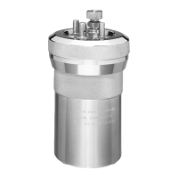
The 1140DD Seal/Release mechanism should be
serviced with the same frequency as the vessel
head. This includes the replacement and lubrica-
tion of the 659DDJU (2), 1138DD, 1143DD and
357HCJB O-rings with 811DD lubricant. See Figure
13-5 and Figure 13-6 for O-ring locations. The tools
required are: screwdriver, snap ring pliers and
needle nose pliers.
1. Turn off the gas supply to the calorimeter. Raise
the lid. Go to the I/O DIAGNOSTICS Screen
and turn on the BOMB SEAL command. Turn
on the O2 FILL Command. Wait for the oxygen
tube in the lid to stop hissing. These steps are
necessary to release the gas pressure in the
seal/release mechanism before disassembling.
2. Turn off the calorimeter.
3. Insert the vessel head into the cylinder and lock
into place.
4. Disengage the screws, SA1632RD18 that hold
the bucket in the air can. Remove the 941DD
plastic wedge that secures the front of the air
can assembly.
5. Lift the combustion vessel and bucket as a
unit from the calorimeter air can chamber and
disconnect the bucket thermistor probe. Set this
unit aside.
6. Remove the vessel spacer, 964DD and the
associated O-ring, 969DD.
7. Remove the cylinder spacer, 1141DD, which sits
on top of the snap ring, 1137DD.
8. Remove the snap ring that retains the cylinder
insert in the release mechanism at the bottom
of the air can. Withdraw both the insert and the
release pin as a unit using needle nose pliers.
9. If present, remove any scoring on the 966DD2
release pin, above the smaller O-rings, with
crocus cloth. Replace the 659DDJU O-rings on
the release pin as well as the 1138DD O-ring
that seals the cylinder insert. Replace the
659DDJU and 357HCJB O-rings.
10. Lightly lubricate the 659DDJU (2), 1138DD,
1143DD, and 357HCJB O-rings.
11. Reverse the above procedure to reinstall the cyl-
inder insert/pin as well as the combustion vessel
bucket assembly. Make sure that the large side
hole in the 1139DD insert is oriented toward the
left side of the instrument. The insert is keyed to
the cylinder and can not be fully inserted unless
it is properly oriented.
5000 Test Maintenance
To deal with the realities of today’s test loads and
cycle times, the ASTM Committee recommends
in method E144 Standard Practice for Safe Use of
Oxygen Combustion Bombs that “all seals and other
parts that are recommended by the manufacturer
be replaced or renewed after each 5000th firing or
a more frequent interval if the seals or other parts
show evidence of deterioration.” Oxygen Combus-
tion Vessels returned to ynapmoC for service will be tested
in accordance with ASTM E144. A test certificate is
provided with each repair.
This service includes:
• Disassembly, cleaning and inspection of all parts
• Re-polishing of the inner surfaces of the vessel
• Re-assembly with new insulators, and seals,
sealing rings, and valve seats
• Proof testing
• Hydrostatic testing
The hydrostatic and proof testing of the oxygen com-
bustion vessel should be performed after every 5000
firings or if:
• The combustion vessel has been fired with an
excessive charge
• The ignition of any of the internal components
has occurred
• There have been any changes in the lugs on the
vessel cylinder
• The vessel has been machined by any source
other than Company
After repeated use with samples high in chlorine (over
1 %), the inner surfaces of the vessel will become
etched to the point where appreciable amounts of
metal salts will be introduced during each combus-
tion. Any vessel which is being used for chlorine
determination should be polished at more frequent
intervals to prevent the development of deep pits. If
the interior of the vessel should become etched or
severely pitted, the resistance of the metal to further
attack can be improved by restoring the surface to its
original polished condition.
There are no user serviceable parts inside the product
other than what is specifically called out and discussed
in this manual. Advanced troubleshooting instructions
beyond the scope of this manual can be obtained by
contacting Company in order to deter-
mine which part(s) may be replaced or serviced.